
1. Foreword & Machine Specifications
Foreword
We thank you for choosing Rownd CNC Lathe. just one last step left for you to unleash your creativity. This manual instructs you to use -enjoy- the Rownd CNC Lathe. For the best experience, please read this manual carefully and strictly follow the instructions.
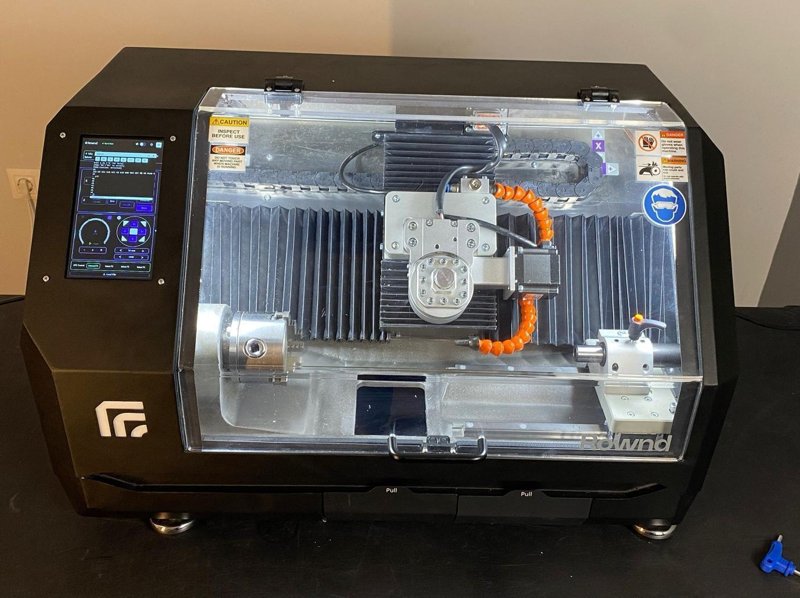
Machine Structure Diagram
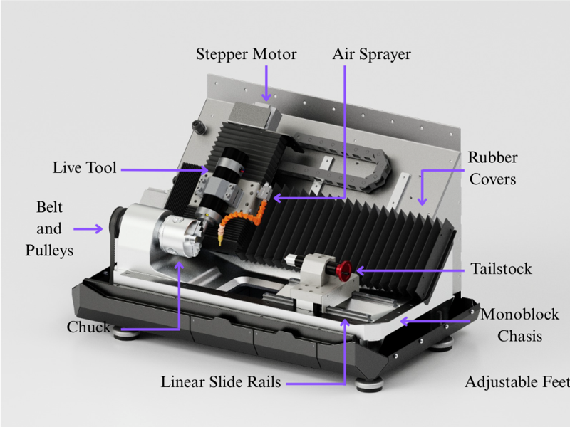
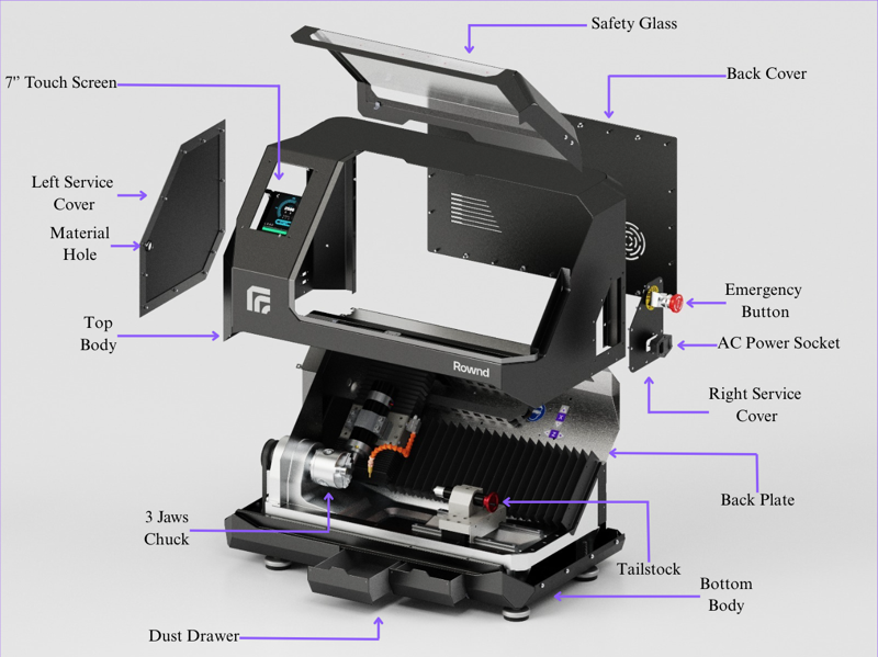
Machine Specifications
| Category | Specification | Value / Description |
|---|---|---|
| Body | Max. workpiece diameter | 135 mm (5 1/4 inch) |
| Max. workpiece length | 290 mm (11 27/64 inch) | |
| Max. workpiece weight | 6 kg (13.2 lb) | |
| Chuck Diameter | 80 mm (3 1/4 inch) | |
| X-axis travel | 110 mm (4 1/4 inch) | |
| Z-axis travel | 320 mm (12 1/2 inch) | |
| Tailstock travel | 190 mm (7 1/2 inch) | |
| Chassis & shell materials | Aluminum, Stainless Steel | |
| Speed | Chuck speed | 0–3000 RPM |
| Spindle speed | 5100–12000 RPM | |
| Max. movement speed | 1000 mm/min | |
| Max. feed rate | 1000 mm/min | |
| Tool System | Tool size | 10x10 mm (3/8x3/8 inch) |
| Tailstock taper | MT1 | |
| Tailstock sleeve diameter | 20 mm (3/4 inch) | |
| Chuck through-hole | 12 mm (1/2 inch) | |
| ATC tool positions | 4-position | |
| 4th axis spindle type | ER11 | |
| Dimensions | Machine dimensions | 770x470x470 mm (30x18x18 inch) |
| Packing dimensions | 870x580x620 mm (34x23x24 inch) | |
| Weight (Net/Gross) | 55/68 kg (120/150 lb) | |
| Precision | Positioning accuracy | 0.02 mm (0.0008 inch) |
| Repeatability accuracy | 0.02 mm (0.0008 inch) | |
| Angular Repeatability | 0.1 degree | |
| Power | Spindle motor power | 750 W |
| 4th axis spindle power | 400 W (Optional Add-on) | |
| Laser engraver power | 10 W (Optional Add-on) | |
| Voltage & frequency | 100–240 VAC, 50/60 Hz | |
| Max power consumption | 1200 W @220V, 1400 W @110V | |
| Electronics | Display | 7-inch Mmulti-Touch Screen |
| Connectivity | Wi-Fi, Bluetooth, USB Type Mini | |
| Storage | 48 GB internal + USB flash | |
| Control interface | Touchscreen, Mobile App, PC App., Gamepad | |
| Safety & Features | Spindle direction control | Clockwise / Counter-clockwise |
| Emergency stop | Triggered when cover is open | |
| Splash guard | Full-length rubber bellows | |
| Gear system | All-metal, wear-resistant |
2. Labels and Symbols
| Symbol | Explanation | Location |
|---|---|---|
   |
Axis directions. | On the top of the bellows. On the top of the Chuck. |
 |
Indicates the location of the emergency button. | The area around the emergency button. |
 |
Wear safety goggles when operating the CNC function or laser goggles when operating the laser. | On top of the bellows. |
 |
Do not touch any moving part when the machine is running. | On top of the bellows. |
 |
Do not wear gloves when operating this machine. | On top of the bellows. |
 |
Do not touch any moving and rotating parts. | On the top of the chuck. |
 |
Moving parts can crush and cut. Do not operate with the guard removed. | Inside the left hatch. |
 |
Moving parts can crush and cut. Do not operate with the guard removed. | Inside the left hatch. |
 |
Electric shock risk. | Inside the left hatch. |
 |
Keep your hands away from sharp edges and cutting tools. | On the live tool module. On the QCTP module. |
 |
Avoid eye or skin exposure to direct or scattered radiation. | On the laser module. |
 |
Read and understand the user manual before operating this machine. | On the back hatch. |
 |
Electric shock risk. | On the back hatch. |
3. General Safety Instructions
Rownd CNC Lathe is a powerful and precise machine. Like all other electric power tools, it must be used with care. For your own safety, please read the following safety instructions carefully.
General Usage Warnings
- Read this manual carefully before using the Rownd CNC Lathe.
- Always wear protective safety goggles while the device is operating.
- Laser protection goggles must be worn during laser engraving operations.
- Do not forget to wear hearing protection when working with hard materials.
- Always keep the protective cover closed. Do not place your hands near the spindle or the machining area.
- Never touch moving parts while the device is operating.
- Do not operate the machine when tired or under the influence of medication, alcohol, or drugs.
- Do not hold the workpiece with your hands during cutting or carving. Always make sure it is securely clamped in place.
- After using the spindle or QCTP, avoid touching or removing parts immediately, as surfaces may still be hot.
- Ensure a fire extinguisher is nearby at all times during operation.
Working Environment and Conditions
- Use the device indoors only, on a solid and level workbench or table.
- Do not expose the machine to rain or high humidity.
- Operate in a well-ventilated area. If using the laser
- Do not leave the machine unattended while it is powered on.
- Keep children away from the device during operation. Children may only use it under direct adult supervision.
- Remove any reflective materials from the work area, especially when operating the laser module, to avoid scattered radiation.
Maintenance and Emergencies
- Always turn off the power before performing any maintenance or modifications.
- In case of emergency, press the emergency stop button first. This will immediately cut off power and allow safe intervention.
- Turn off the machine immediately if any of the following occur:
- Unexpected machine stop
- Visible damage to interior components
- Any unusual light, sound, or smell
- The QCTP, tools, cutters, or workpiece becomes jammed.
- If using an air sprayer:
- Use only clean, dry compressed air.
- Do not spray toward people or electronics.
- Always connect a compatible air compressor before enabling the nozzle.
- Ensure the air adjustment valve is fully closed before connecting the compressor.
Laser Safety
- Always wear laser safety goggles during operation.
- Never expose yourself or others to the laser beam.
- Operate the laser in a well-ventilated space or use an air purifier.
- Make sure a fire extinguisher is nearby during laser operations.
- Remove any reflective materials from the work area to prevent scattered laser radiation.
- Turn off the Rownd CNC Lathe immediately if any of the following occur during laser operation
- Open flames appear
- Unexpected machine stop
- Visible damage to internal laser components
- Unusual light or sound not previously experienced during engraving
4. Part List & Work Environment
Some of the equipment included with the machine comes pre-installed on the machine, while others are provided separately in the box. Both groups are described below.
List of the Items on the Machine 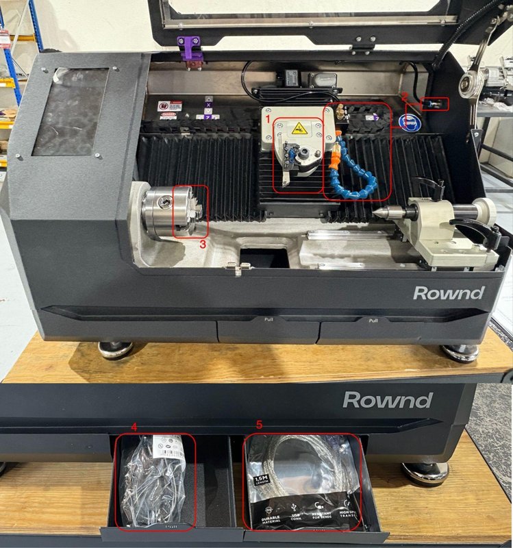
1- QCTP with QCTP holder
2- Air Cooling System*
3- Chuck
4- Power Cable 1.8 Mt.
5- USB to USB Cable
*Included only if the Air-Cooling add-on has been purchased.
List of the Items in the Box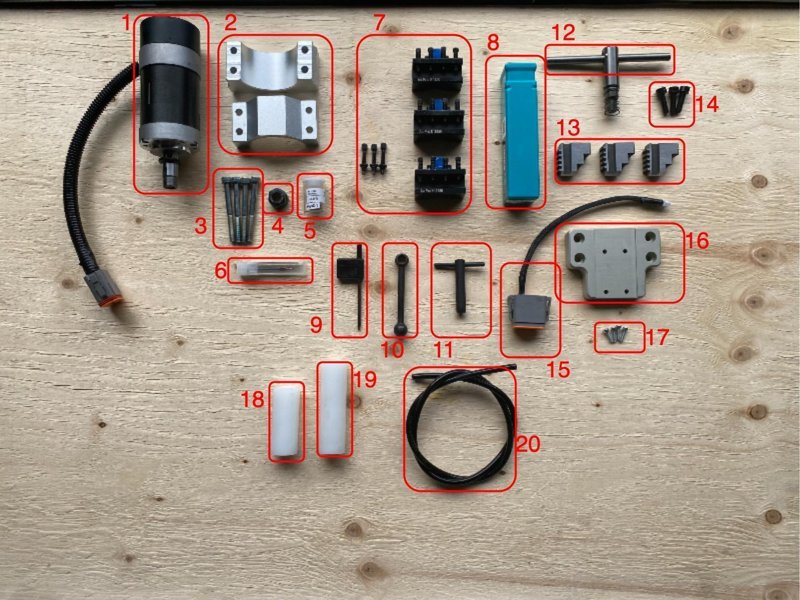
- 1 x 400W 4th Axis Add-on motor*
- 1 × Live Tool Holder Set*
- 4 × M6x60 DIN912 Bolts (For Attaching the Live Tool to the wedge with a Live tool holder set)*
- 1 × ER11 Nut*
- 1 × ER11 Collet*
- 1 × Ball end mill (3-Flute)*
- 2 × 4-sided Grooved QCTP, 1 × V-grooved QCTP, 3 × QCTP Tool Holder Bolts
- 1 × 10×10 left-Hand External Turning Toolbox (Tool is mounted on your machine.)
- 1 x Torc Key
- 1 × QCTP Wrench
- 1 × Tool Holder Wrench
- 1 × Chuck key
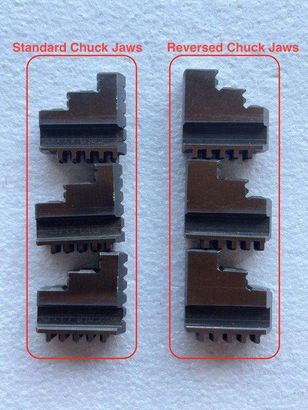
- 1 x Set (3 pcs) Reversed Chuck Jaws
- 3 × M6x20 DIN912 Bolts
- 1 × Laser Cable**
- 1 × Laser Holder**
- 4 × M3x10 DIN912 Bolts (For attaching the laser to Laser Holder)**
- 1 x Test Sample for Lathe Mode
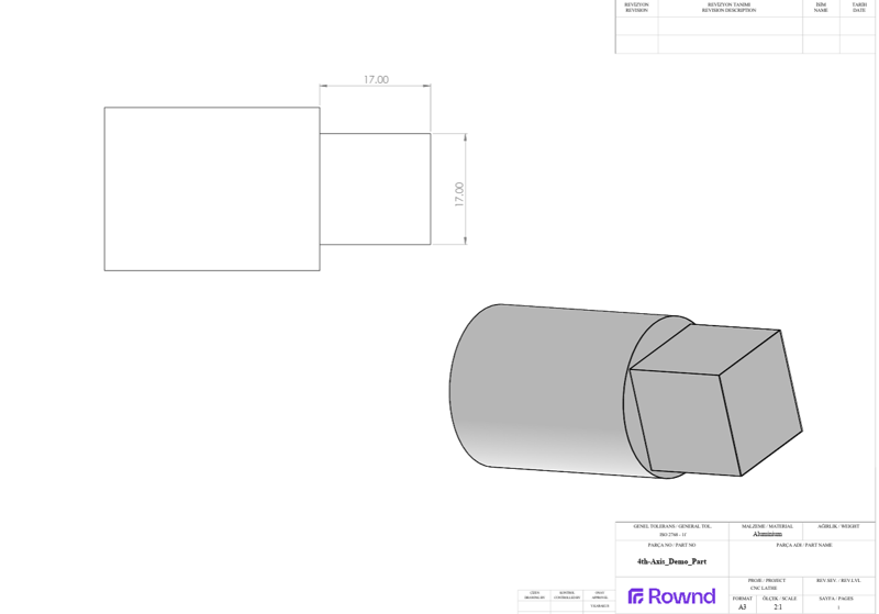
- 1 x Test Sample for 4th-Axis Mode*
- 1 x Extension Tube for the Air-Cooling System***
*Included only 4th Axis add-on.
***Included only if the Air-Cooling add-on.
Before operating your machine, ensure that your workspace is suitable:
-Make sure your machine is placed on a flat surface.
-Operate your machine in a dry location, away from moisture and the risk of getting wet.
-Ensure there is enough space on the right side of your machine to easily access the emergency button.
-Ensure that the workbench is placed in a well-ventilated area.
-Make sure that a fire extinguisher is available in the working area.
5. Material Library & Speeds/Feeds
Your Rownd CNC Lathe stands out as a machine with a comprehensive machining material library. You can machine materials up to a maximum weight of 6 kg for lathe mode, with a diameter of 135 mm and a length of 285 mm on your machine.
The materials that can be processed by your machine in Lathe and 4th axis modes include:
-Wood
-Aluminum
-Brass
-Copper
-Bronze
-Epoxy Resins
-Steel up to 45 HRC*
-Titanium up to Grade-5*
*Air cooling can be used for all type of materials but especially hard materials like steel, iron or titanium needs air cooling for surface quality.
In laser mode, various wood and plastic materials can be used.
Cutting Tool Definitions
Below are guideline-level information for the five basic turning operations: rough machining, finish machining, grooving/cutting, threading, and drilling. This information has been primarily prepared with beginner users in mind. The values given here should not be considered as absolute optimum values.
| Roughing Rough machining is the initial process performed to remove a large amount of material from the workpiece surface. The goal is to quickly form the desired general shape. Tool Use: The roughing tool operates with high cutting depth and feed rate. Its tip geometry is robust and has a rigid structure. |
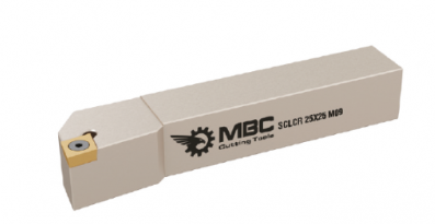 |
|---|---|
| Finishing After rough machining, finishing is performed with lower cutting depth and feed rate. It is done to improve surface quality and achieve precise dimensions. Tool Usage: Cutters with sharper and more precise edges are used. The amount of material removed is small, and surface quality is prioritized. |
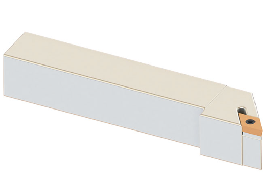 |
| Grooving - Parting Off This operation is performed to create a groove on the workpiece or to completely separate the part. Tool Usage: Special narrow and long grooving cutters are used. For cutting operations, special tips called cutting blades are preferred. |
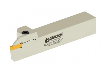 |
| Threading This operation is performed to create screw threads. Both internal and external threading can be done. Tool Usage: Special cutting tips suitable for the thread form (e.g., metric, trapezoidal, etc.) are used. Precise feed rates are required. |
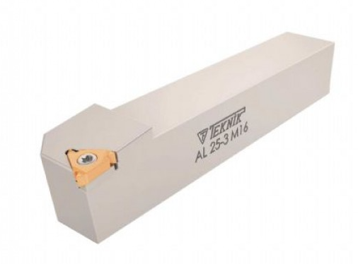 |
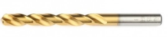
| Drilling This operation is performed to create a hole at the center of the workpiece on a lathe. Tool Usage:It is typically carried out using drill bits that are held stationary (drill bits mounted on the lathe).The drill bit is advanced into the rotating workpiece to form the hole. |
 |
Lathe Mode Cutting Parameters
The tables below provide reference values for machining different materials. Each table is prepared according to a specific material type. The values presented are recommended safe starting points. As general lathe process knowledge and familiarity with the machine increase, users can optimize these values accordingly.
- Hard Metals (Steel, Stainless Steel, Titanium, etc.): Coated cutting inserts with a 0.2 mm nose radius must be used.
- Soft Materials (Wood, Plastic, Aluminum, Brass, Copper, etc.): Uncoated cutting inserts should be used, with a nose radius between 0.2 mm and 0.4 mm.
| Operation | Workpiece Diameter | Feed Rate (f) | Chuck RPM | Cutting Depth | Cutter Type |
|---|---|---|---|---|---|
| Roughing | 5mm-20mm | 300–400 mm/min | 2500-3000 RPM | 0,2-0,3 mm | HSS |
| 20mm-40mm | 250-350 mm/min | 2000-2500 RPM | 0,3-0,5 mm | HSS | |
| 40mm-80mm | 200-250 mm/min | 1800-2000 RPM | 0,5-1 mm | HSS | |
| Finishing | 5mm-20mm | 100-200 mm/min | 3000 RPM | 0,05-0,1 mm | HSS |
| 20mm-40mm | 75-120 mm/min | 2500-2800 RPM | 0,05-0,1 mm | HSS | |
| 40mm-80mm | 50-100 mm/min | 2000- 2500 RPM | 0,05-0,1 mm | HSS | |
| Grooving Parting Off | 5mm-20mm | 100-150 mm/min | 2000-2500 RPM | 0,1-0,2 mm | HSS |
| 20mm-40mm | 75-120 mm/min | 1800-200 RPM | 0,2-0,3 mm | HSS | |
| 40mm-80mm | 50-75 mm/min | 1500-2000 RPM | 0,3-0,5 mm | HSS | |
| Drilling | 2-5 mm | 250-300 mm/min | 2000-2500 RPM | 1 mm Peck drilling | Uncoated drill |
| 5-10 mm | 200-250 mm/min | 1800-2000 RPM | 2 mm Peck drilling | Uncoated drill | |
| 10-12 mm | 150- 200 mm/min | 1500-2000 RPM | 3 mm Peck drilling | Uncoated drill |
WoodPlastic (PA, POM, PET etc.)
| Operation | Workpiece Diameter | Feed Rate (f) | Chuck RPM | Cutting Depth | Cutter Type |
|---|---|---|---|---|---|
| Roughing | 5mm-20mm | 300–400 mm/min | 2500-3000 RPM | 0,2-0,3 mm | HSS |
| 20mm-40mm | 250-350 mm/min | 2000-2500 RPM | 0,3-0,5 mm | HSS | |
| 40mm-80mm | 200-250 mm/min | 1800-2000 RPM | 0,5-1 mm | HSS | |
| Finishing | 5mm-20mm | 100-200 mm/min | 3000 RPM | 0,05-0,1 mm | HSS |
| 20mm-40mm | 75-120 mm/min | 2500-2800 RPM | 0,05-0,1 mm | HSS | |
| 40mm-80mm | 50-100 mm/min | 2000- 2500 RPM | 0,05-0,1 mm | HSS | |
| Grooving Parting Off | 5mm-20mm | 100-150 mm/min | 2000-2500 RPM | 0,1-0,2 mm | HSS |
| 20mm-40mm | 75-120 mm/min | 1800-200 RPM | 0,2-0,3 mm | HSS | |
| 40mm-80mm | 50-75 mm/min | 1500-2000 RPM | 0,3-0,5 mm | HSS | |
| Drilling | 2-5 mm | 250-300 mm/min | 2000-2500 RPM | 1 mm Peck drilling | Uncoated drill |
| 5-10 mm | 200-250 mm/min | 1800-200 RPM | 2 mm Peck drilling | Uncoated drill | |
| 10-12 mm | 150- 200 mm/min | 1500-2000 RPM | 3 mm Peck drilling | Uncoated drill |
Aluminum
Brass
Copper
Steel (1040–1050 etc.)
Stainless Steel (AISI 304, 316 etc.)
Titanium (Grade-5 / Ti-6Al-4V)
6. Power-on Guide & Machine Setup
This section will help you through the setup and steps. You will find the power cable inside the right drawer of the machine.
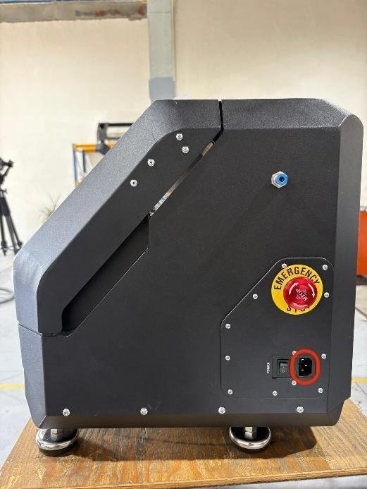
| 1. Plug one end of the power cable into the power socket on the machine and the other end into a wall outlet. Note: Please plug your machine into a single outlet. If you connect it to a multi-outlet, make sure no other devices are plugged into it. Note: Do not use an extension cord. If you must use one, ensure that only your machine is connected to it and make sure the extension cord has a current carrying capacity of at least 10 Amps. |
 |
|---|---|
| 2. Turn the emergency stop button to release it. | 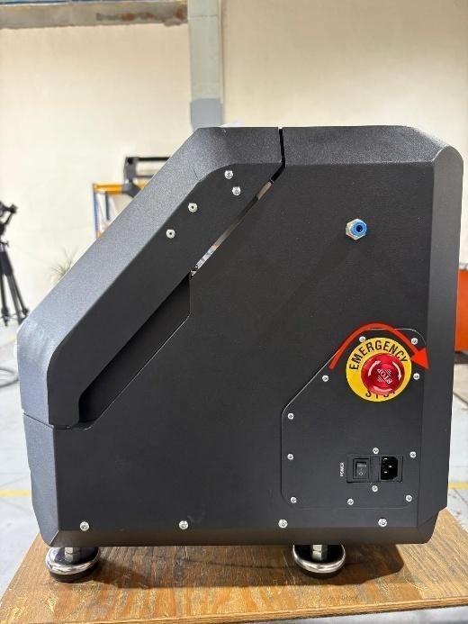 |
| 3. Switch on the power button and then, check that the internal lights of the machine are functioning. | 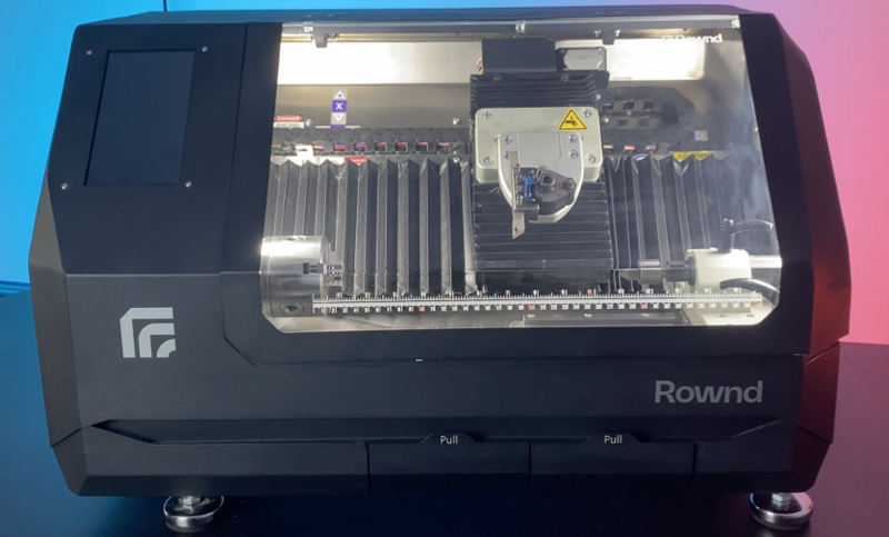 |
| 4. After pressing the power button, wait for the machine to start up and for the Rownd application to appear on the screen. |  |
|---|---|
| 5. Connect a mouse to the USB port on your machine. | 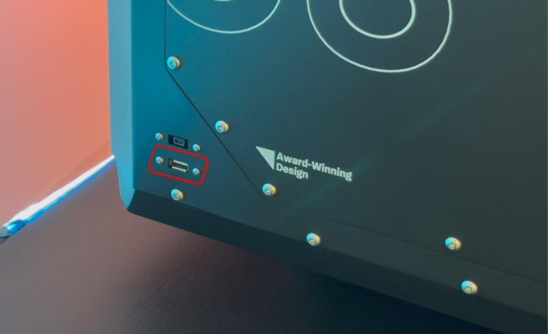 |
| 6. Click the Raspberry icon in the top-left corner. From the menu, go to Accessories and tap the Screen Keyboard. |
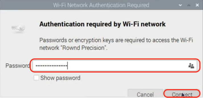
| 7. Click the Wi-Fi icon and select the network you want to connect to and enter the password of the network with the screen keyboard. | 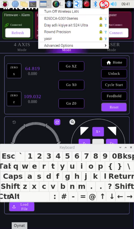 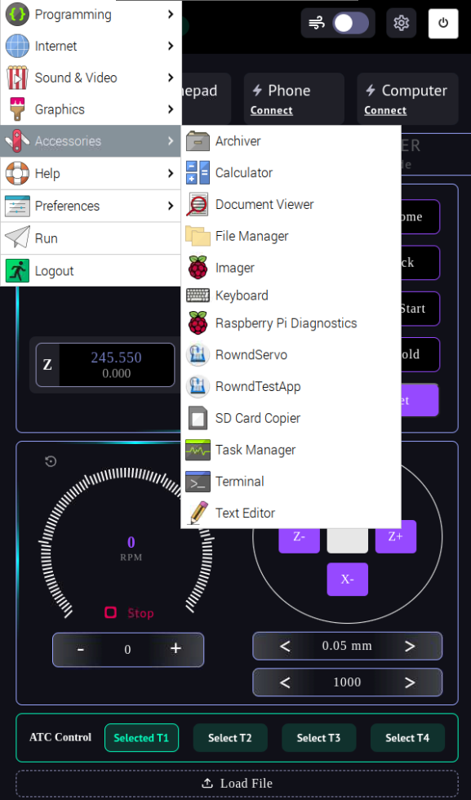 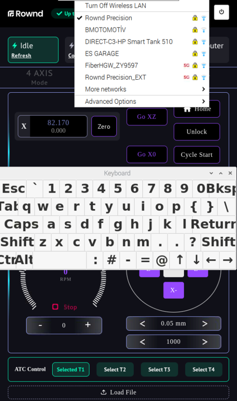 |
|---|---|
| Note: At this stage, it is recommended to install any available updates. | |
 |
|
| 8. Tap the Home button on the touchscreen and send your machine to the Home position. | 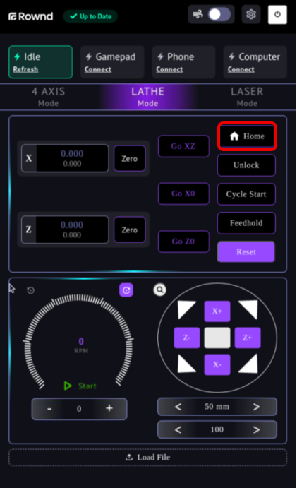 |
Note:The required position of the machine after the homing procedure is as shown in the illustration. |
| 9. After the homing process is complete, tap the Load File button. | 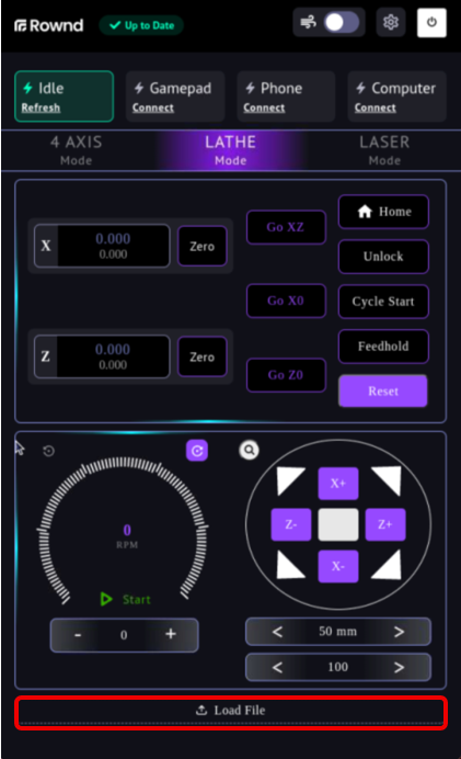 |
|---|
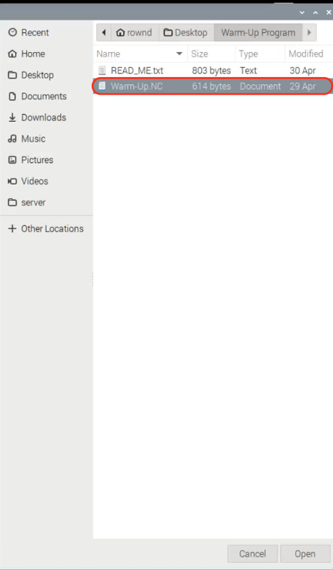
| 10. Select Desktop, then navigate to the Warm-up Program folder and open the “Warm-Up.NC” file and tap Run button. | 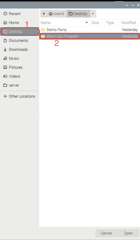 |
 |
|---|---|---|
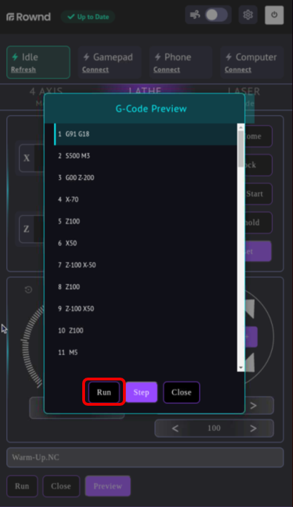
| Note: If you’d like to see the code that you will run, you could tap the Preview button. | 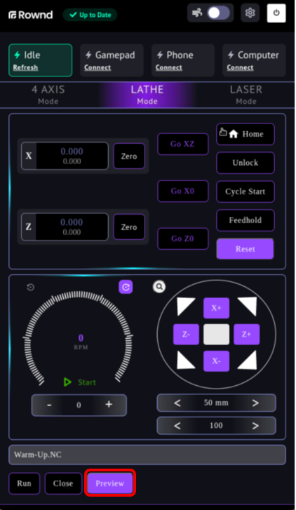 |
 |
Moving closer to the chuck may cause the cutting tool to hit the chuck. For this reason, make sure the Warm-up program is not run during demo part machining.
Display Mode & KVM Switch
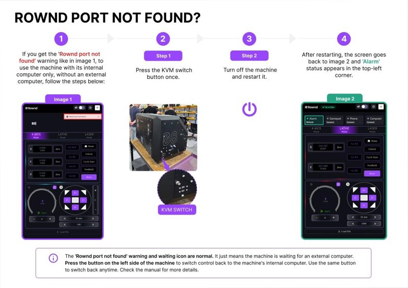
The KVM switch allows you to switch the screen and controls between the machine’s internal computer and an external PC. If you see the “Rownd port not found” message with the loading icon at startup, don’t worry. This simply means that the machine is in external PC mode.
To use the machine with its internal computer only, without an external PC, follow the steps below:
- Press the KVM Button: Press the button on the left side of the machine once.
- Restart the Machine: Turn off the machine and restart it.
Once restarted, the main Rownd screen will appear with the " Alarm" status in the top-left corner.
How to Use
This section explains how to operate your machine, perform the setting zero process, mount the workpiece, and many other important procedures. It is strongly recommended that you read this section entirely.
Machine States
Machine states indicate the current operational condition of your machine and show which process is being performed at that moment. This information is displayed in the top-left corner of the screen, right next to the label “Firmware”. Regardless of whether the machine operates in 4th Axis, Lathe, or Laser mode, each of these states is considered valid.
Machine modes define the intended use of the machine, whereas machine states reflect its current working condition.
The possible machine states are as follows:
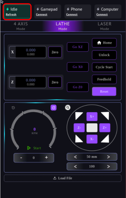
| Idle: It indicates that your machine is in the Idle state and ready to operate. In this state, the axis limit switches have not been triggered, and there is no active software alarm. The Idle state shows that all position-controlled axes (X, Z, or C) are stationary and not in motion. In this state, the spindle (during lathe mode) and the live tool can rotate. Note: In this state, you can switch between 4th Axis, Lathe, and Laser modes. |
 |
|---|---|
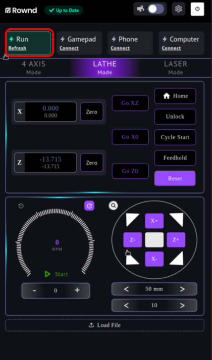
| Run: The machine is in 'Run' mode while the X, Z, and C axes are in motion or when the G-code is being executed. During this time, at least one of the axes operating under position control moves according to the given commands. |
 |
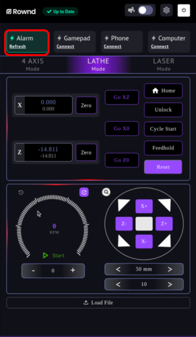
| Alarm: It indicates that your machine has encountered an alarm condition. For safety reasons, your machine starts up in Alarm mode. While in this mode, you cannot issue any motion commands or switch between 4th Axis, Lathe, and Laser modes. The machine enters this mode when it is first powered on, when a fault occurs, when the reset button is pressed, or when any of the axis limit switches are triggered. If the machine enters the alarm state, the cause of the alarm should be identified. It is normal for the machine to enter the alarm state when it is first powered on or when the reset button is pressed. If an alarm occurs under other circumstances, there must be another reason triggering the alarm state. |
 |
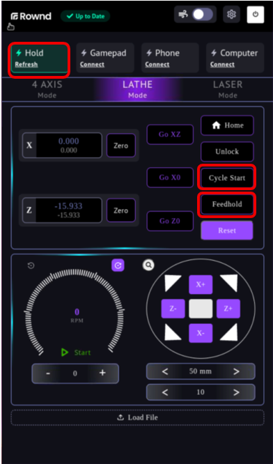
| Hold: This state indicates that the ‘Feed Hold’ button has been pressed or that the M0 command is written in the G-code file currently being executed. When the machine is stopped using the Feed Hold button, it will resume motion from the point where it was paused. To continue the operation, the ‘Cycle Start’ button must be used. Warning: The Reset button is not the same as the Feed Hold button. It stops the machine but does not pause it. When Reset is pressed, all commands related to the current process are canceled, and the machine will not resume from the previous point. |
 |
| Door: It states that the machine’s protective cover is opened. When the machine’s protective cover is closed again, the Door state will continue to be displayed. The system waits for confirmation from the user to ensure that the protective cover has been securely closed. If the machine is in Door state and you want to change it to Idle state, first ensure that the door is closed. Then, to switch to Idle state, first tap the ‘Reset’ button and then tap the ‘Unlock’ button. |
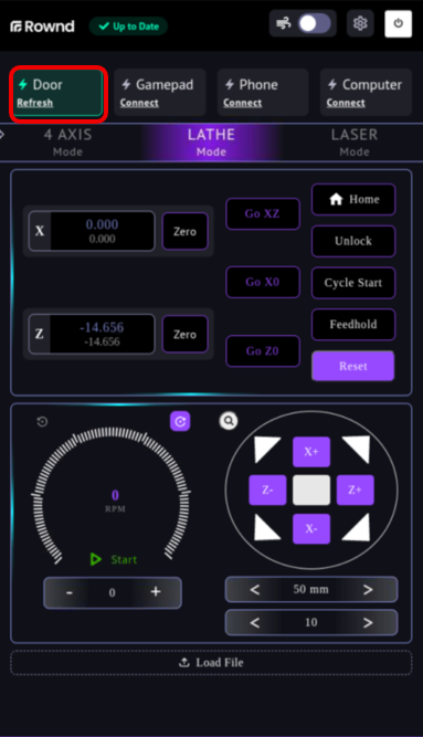 |
| Jog: It states that the machine is in manual control mode, that axis movements are performed via mobile application or gamepad. The machine will remain in this state as long as manual axis movements are performed. |
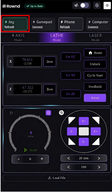 |
| Home: It states that your machine is performing the homing process. Once the homing is successfully completed without any alarms, the machine automatically transitions to the Idle state. If an alarm occurs during homing, the machine switches to the Alarm state instead. Note: It is recommended to perform homing when the machine is first powered on. There is no need to repeat the homing process unless the machine is powered off. |
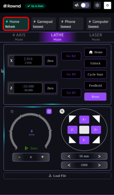 |
Air Cooling
The air-cooling system in your machine is designed to control the heat generated during machining operations. This helps to improve the surface quality of the workpiece and extend the performance and lifespan of the cutting tool. The system provides effective cooling and chip removal by directing compressed air to the cutting area.
Using the air-cooling system is especially recommended when machining hard materials.
The cooling system operates through a flexible hose that could be positioned towards the cutting tool.
| First, connect the compressed 6mm air hose to the air inlet fitting on the machine.A manual adjustment valve is also located to the left side machine and near to the 6mm air hose, as shown in the image below. | 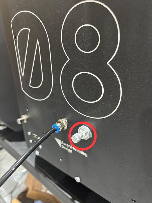 |
|---|---|
| Turn the air cooling on or off as needed. This can be done directly from the screen using the air cooling control, or through G-code: command M7 turns the air cooling on, and command M9 turns it off. | 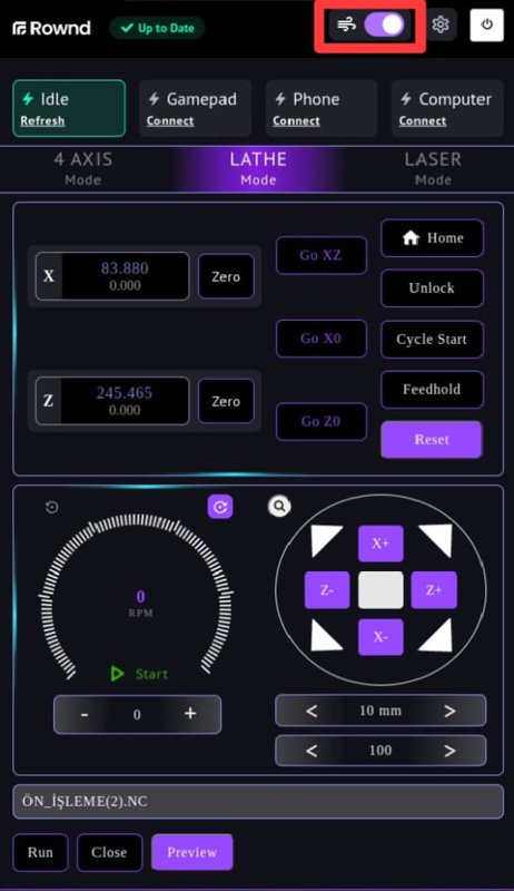 |
| Position the flexible hose so that it points toward the tip of the cutting tool. Make sure the nozzle is neither too close nor too far from the tool, and that its position does not interfere with the tools during tool-change operations when using the ATC (Automatic Tool Changer). Note: The ideal distance is between 3–5 cm, but the positioning may differ depending on the shape of the cutting tool and the geometry of the workpiece | 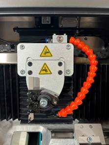 |
Emergency Popup
When the Emergency Stop button is pressed, the program and all axis motion stop immediately, and the following alert appears on screen:
This popup is informational only and has no on-screen button to click — it closes automatically once the physical Emergency Stop button is released. Pressing the button stops the running program and motion, but does not cut electrical power: the screen, control boards, and memory stay powered, so no program or position data is lost.
On machines with serial number [Serial No: 101-2408-10168 ] and above, pressing the Emergency Stop button additionally cuts electrical power specifically to the motors, as an added hardware safety measure, while the screen and control boards remain powered.
In all cases, releasing the Emergency Stop button returns the machine to Ready state, and operation can resume from where it stopped.
When an axis reaches its physical limit switch during a move, motion on that axis stops immediately and the following alert appears on screen (example shown for the X+ axis; the same popup appears for any axis/direction, with the title and message updated accordingly):
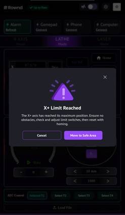
The popup has three buttons: Move to Safe Area, Close (×), and Cancel. In most cases, Move to Safe Area is the button that should be pressed: it automatically moves the axis 5 mm away from the switch, clearing it so that motion is allowed again. The axis cannot be moved further while it remains on the limit switch — it must be cleared by at least 5 mm before movement is allowed again.
Close (×) and Cancel, located in the top-right corner, simply close the popup and leave the axis exactly where it is, still on the limit switch. These should only be used instead of Move to Safe Area in extreme situations — for example, if the workpiece is very large and moving the axis automatically would risk a collision. In that case, the same 5 mm clearance must be achieved manually (e.g. by jogging the axis away from the switch) before further movement is possible
Single Step Execution
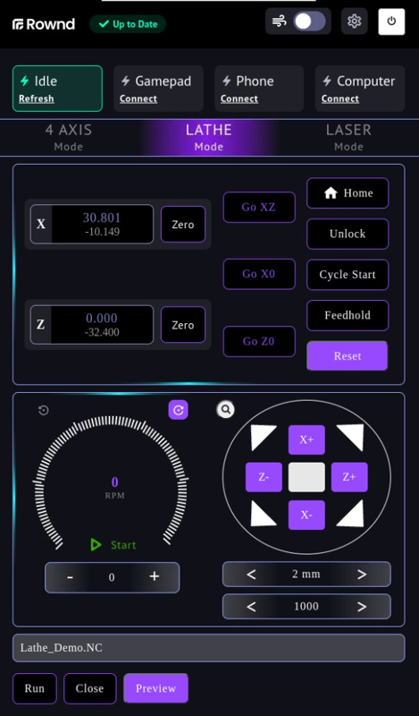
After a G-code program is loaded, its file name appears in the program bar along with the Run, Close, and Preview buttons.
Pressing Preview opens the G-Code Preview window, which lists the loaded program line by line and highlights the current line. This window has three buttons: Run, Step, and Close.
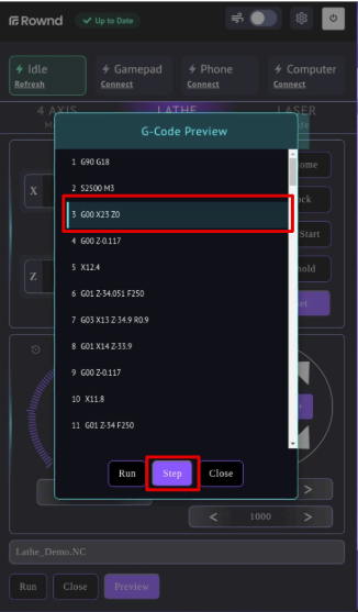
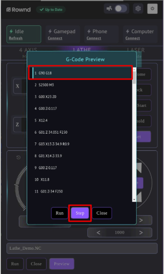
Step executes the program one line at a time — each press of Step runs the next line and highlights it. This allows the program to be checked step by step before running it fully.
After running as many lines as needed with Step, pressing Run switches the machine to continuous execution and runs the remainder of the program automatically. Close closethe G-Code Preview window without affecting the loaded program.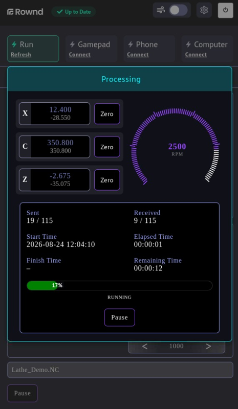
First Experience
To learn the basic controls of the machine, follow the steps below in order and read their explanations. During these operations, the machine will be in Lathe mode. However, detailed information about Lathe mode is provided at 8.5 Lathe Mode below.
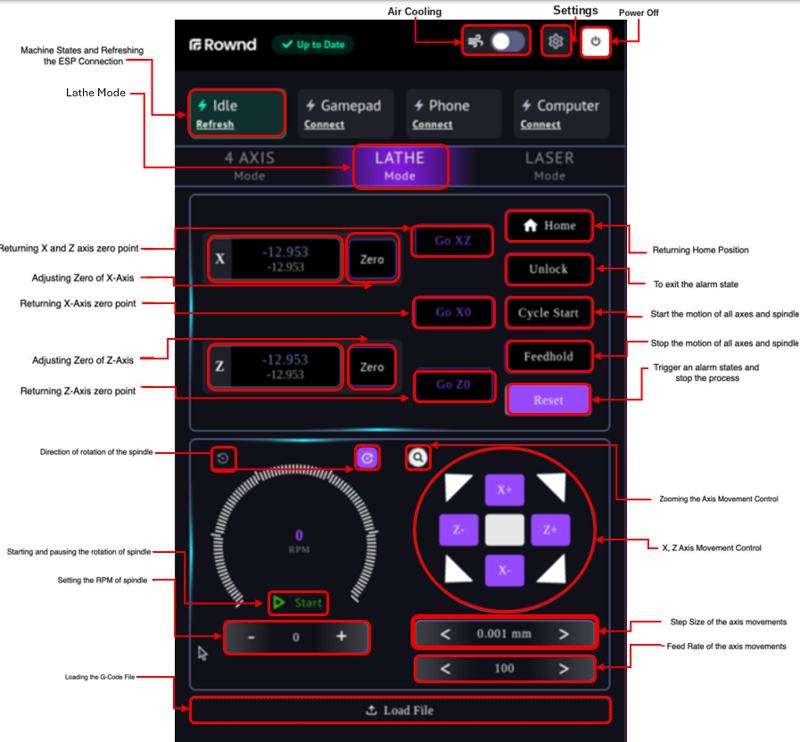
-. Power on your machine.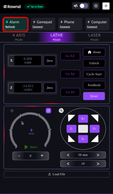
- Click the Home button and watch your machine move first upward, then to the right, reaching the reference coordinates. Wait for the machine to complete its movement.
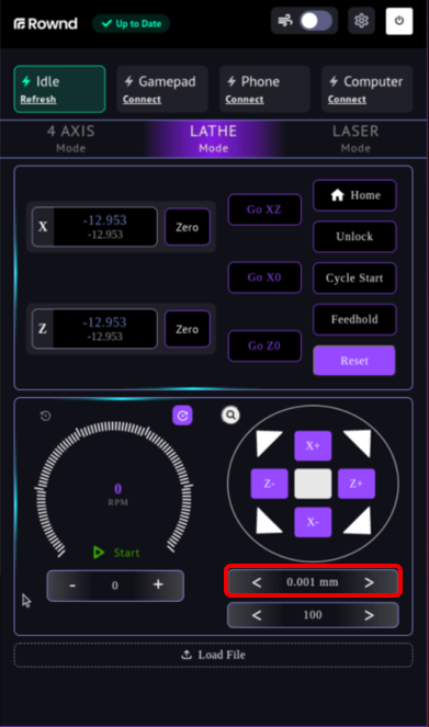
There are three basic parameters to control your machine’s movements: step size, feed rate, and RPM.
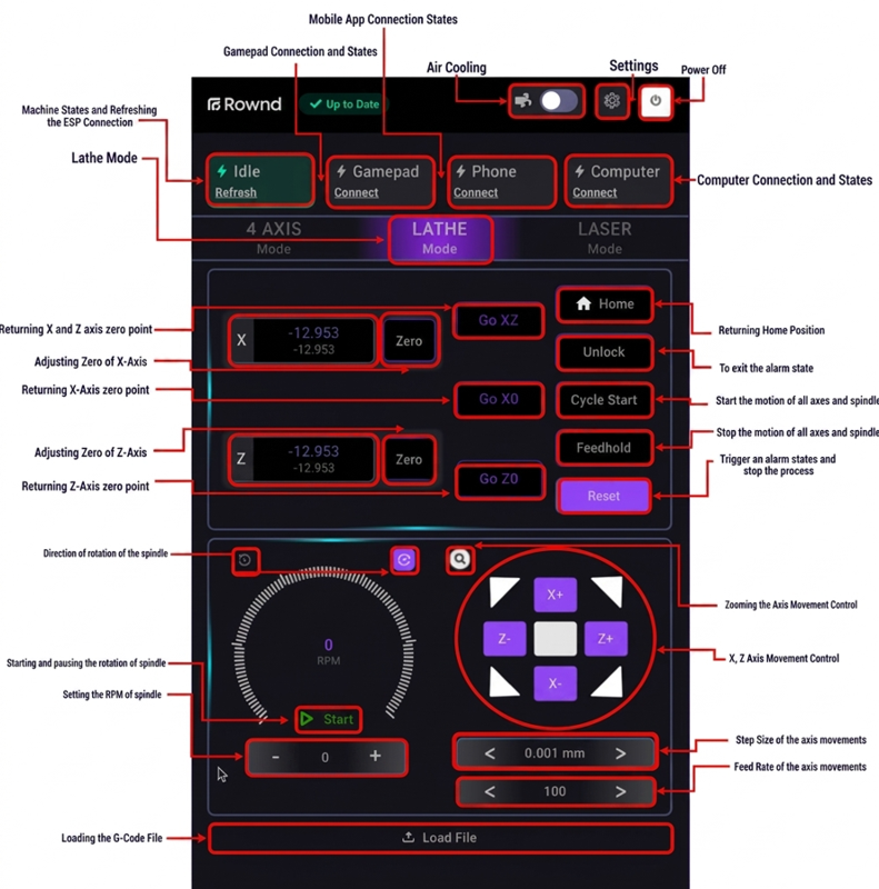
- Step Size: It refers to the distance in millimeters that the machine will move when the linear axis buttons (X-, X+, Z-, Z+) are clicked once. Step size button and its indicator is shown where it is located in the image below.
- Feed Rate: It indicates the speed in millimeters per minute at which the machine will move when the linear axis buttons are pressed. Feed rate button and its indicator is shown where it is located in the image below.
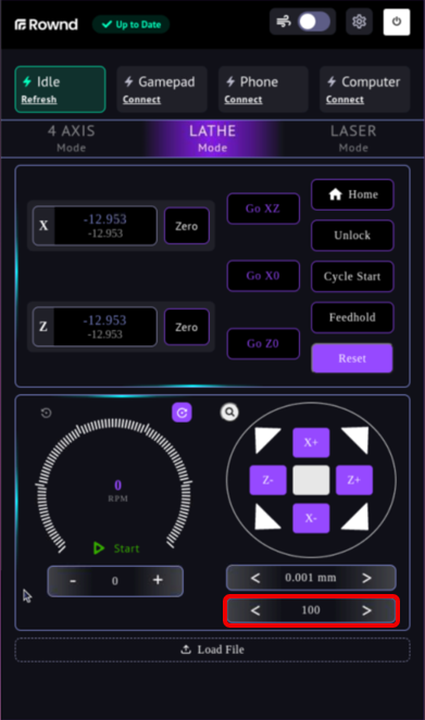
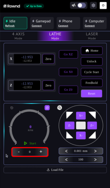
- RPM: It indicates the speed in minutes per revolution at which the spindle will rotate.
RPM button and its indicator is shown where it is located in the image below
Perform the following steps in order.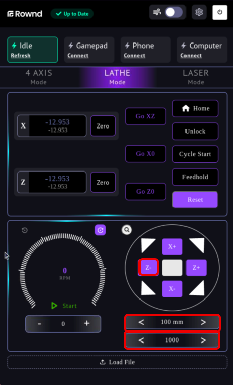
Set the step size to 100 mm and the feed rate to 1000 mm/min, then click the “Z-” button once to move in the -Z direction. Observe the machine moving from right to left.

Set the step size to 50 mm and the feed rate to 1000 mm/min, then click the “Z-” button once to move in the -Z direction. Notice that this movement is half the distance of the previous one. As a result of these actions, you will have moved a total of 150 mm to the left along the Z axis.
Set the step size to 10 mm and the feed rate to 500 mm/min, then click the “X-” button once to move in the -X direction. Observe that the machine moves from top to bottom at half the speed of the previous movement.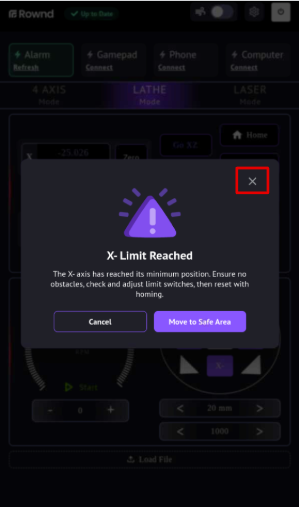
Set the step size to 300 mm and the feed rate to 500 mm/min, then click the “X-” button to move your machine to the lowest point on the X-axis until it touches the limit switch. When the limit switch is triggered, the machine will enter an alarm state as shown in the image below.
Click the "x" icon to close the alarm pop-up. Observe that the machine is in the alarm state. To switch from the alarm state to idle, click the "reset" button followed by the "unlock" button, and verify that your machine has entered the "idle" state. 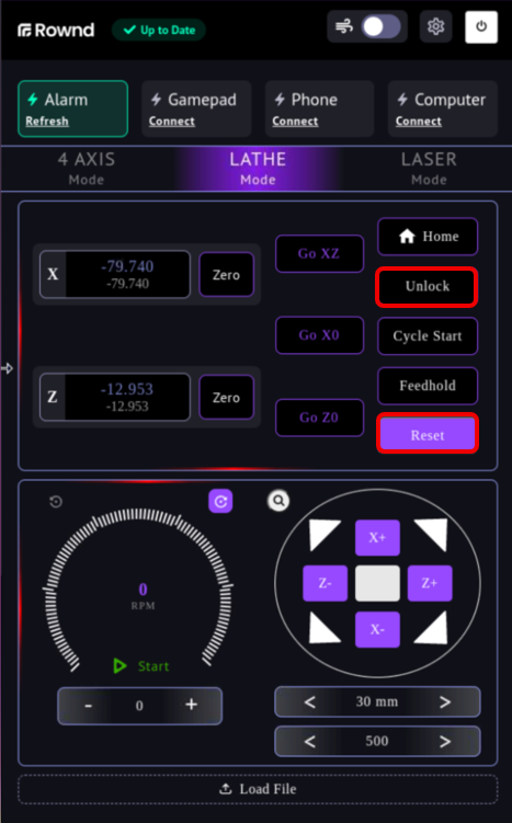
To move the machine away from the switch, set the step size to 50mm and the feed rate to 1000mm/min, then click the “x+” button.Note: When the machine touches the switches during operation, it is recommended to move at least 5mm away before proceeding to the working area.

To understand the function of the other axis buttons, set the step size to 10mm and the feed rate to 300mm/min.
- To move the machine in the -z direction, click the “z-” button once as shown in the image below. Observe that the machine moves 10mm from right to left.
- To move the machine in the +z direction, click the “z+” button once as shown in the image. Observe that the machine moves 10mm from left to right.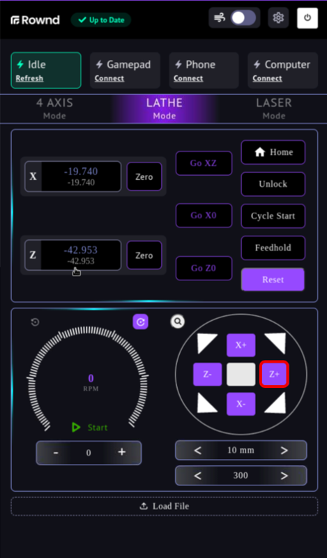
- To move the machine in the +x direction, click the “x+” button once as shown in the image. Observe that the machine moves 10mm from bottom to top.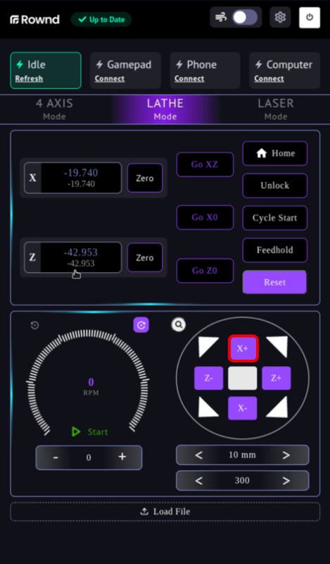
- To move the machine in the -x direction, click the “x-” button once as shown in the image. Observe that the machine moves 10mm from top to bottom.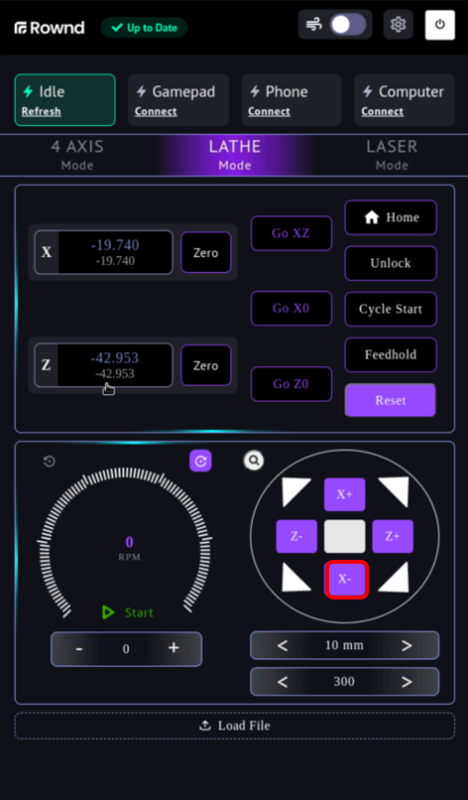
When manually moving the machine, it is important to know the following: If a new axis movement command is given while the machine is still moving and hasn't completed the previous movement, the commands are queued, and the machine continues moving until all commands are completed. To test this, follow the instructions below: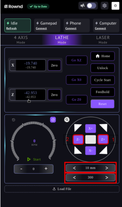
Set the step size to 10mm and the feed rate to 100 mm/min.
Click the “z+” button once to move in the +z direction, and immediately after the machine starts moving, click the “z-” button once. Observe that the machine completes the movement to the right and then immediately moves to the left.
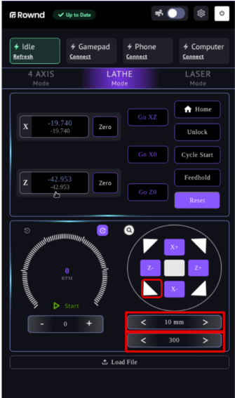
- To observe diagonal axis movements, set the step size to 10mm and the feed rate to 300mm/min, then click the white arrow pointing down-left as shown in the image. Watch the machine move from its current position at a 45-degree angle toward the down-left direction.
- Without changing the step size and feed rate values, click the white arrow pointing up-right as shown in the image. Observe the machine moving from its current position at a 45-degree angle toward the up-right direction.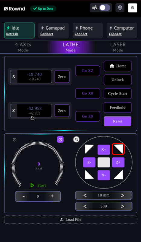
- Click the white arrow pointing up-left as shown in the image. Observe the machine moving from its current position at a 45-degree angle toward the up-left direction.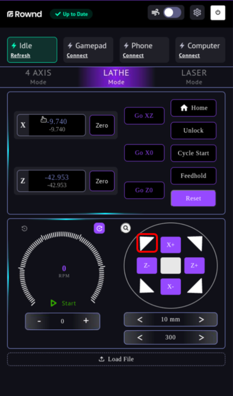
Click the white arrow pointing down-right as shown in the image below. Observe the machine moving from its current position at a 45-degree angle toward the down-right direction.
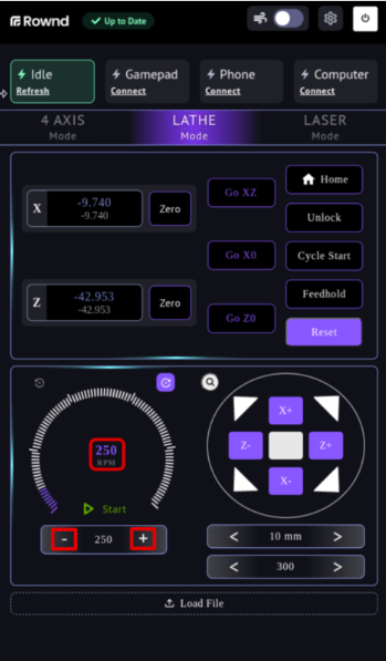
To learn the spindle movements, use the “+” and “-” buttons located below the RPM bar in the marked area to set the speed to 250 RPM. You can either hold the buttons down or click them one by one to increase or decrease the speed.
- Click the Start button to begin rotating the chuck and observe that it rotates clockwise. 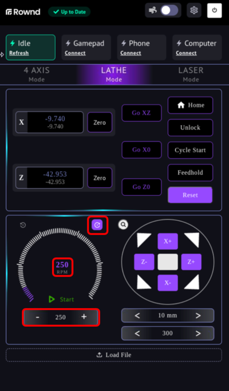
- Press the Stop button to stop the spindle.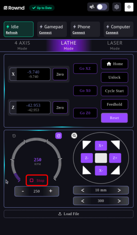
To gradually increase the spindle speed, first press the “Start” button, then use the “+” and “-” buttons to adjust the speed. You can either hold the buttons down or click them repeatedly to increase or decrease the RPM. You can also click on the indicator to set the speed reference.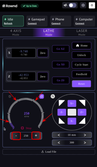
- To stop the spindle, press the “Stop” button.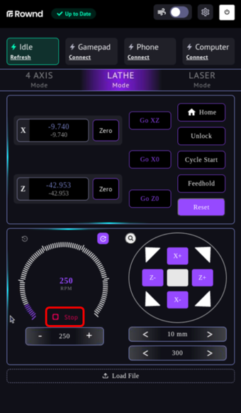
- To rotate the spindle counterclockwise, press the direction button located at the top left of the RPM bar as shown in the image below. You can confirm the direction is selected when the button turns purple. 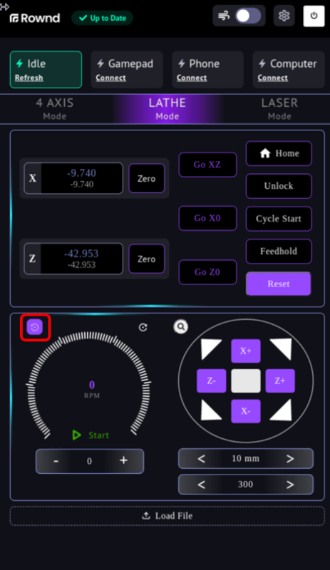
Then, use the “+” and “-” buttons to set the speed to 250 RPM. Click the “Start” button to give the spindle speed and observe that it rotates counterclockwise.Stop” button.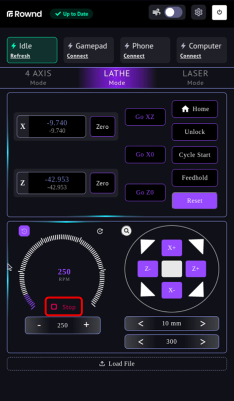
You cannot change the spindle rotation direction while it is moving, or the spindle motor is active. To test this, press the “Start” button and make sure the RPM is at “0”.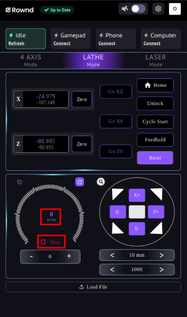
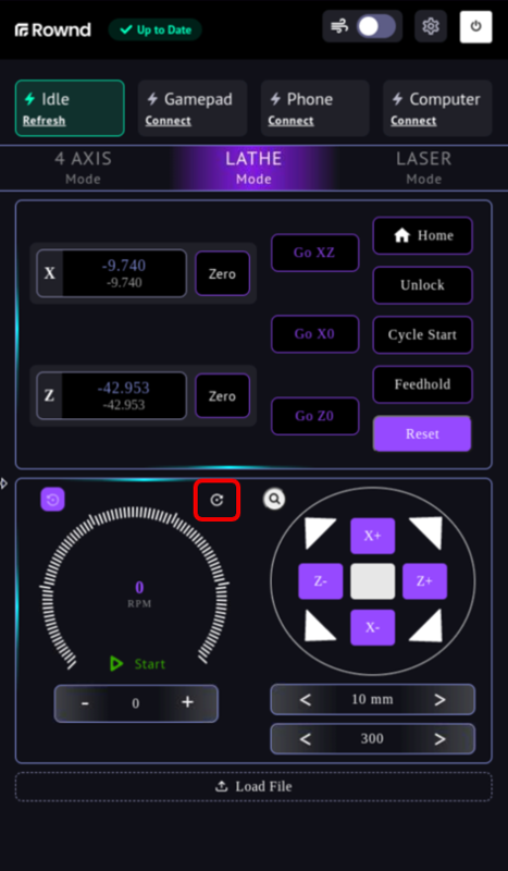
– Then, to change the rotation direction, press the direction button located at the top right of the RPM bar that indicates clockwise rotation, and observe that the button is not active.
- To stop the spindle, press the “Stop” button.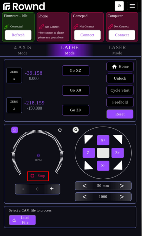
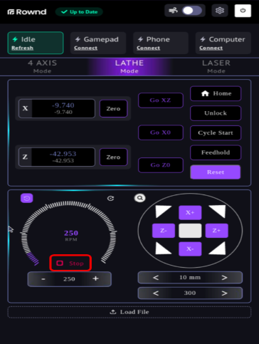
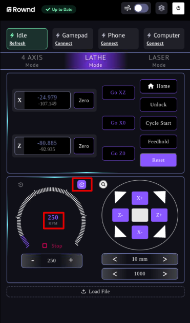
To rotate the spindle clockwise, activate the clockwise rotation button located at the top right of the RPM bar and set it to 250 RPM. Then, click the “Start” button to start the spindle.
In the following steps, you will experience the functions of the “Feedhold”, “Cycle Start,” “Reset,” and “Unlock” buttons.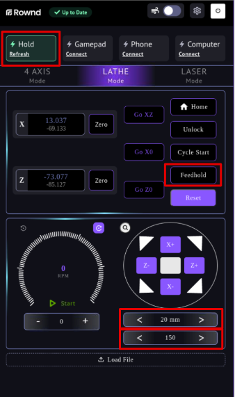
Observe that the axis movements and spindle stop. Notice that the machine state is also “Hold.”
While the machine is in hold state, click the axis movement buttons in the following order: “z-”, “z+”, “x-”, and “x+”, and observe that the machine’s axes do not move.
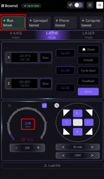
- To complete the given axis movement, click the "Cycle Start" button and observe that the movement continues. During the movement, notice that the machine is in the "Run" state and that the chuck resumes rotating at 250 RPM.
- When the movement is completed, observe that the machine switches to the “Idle” state.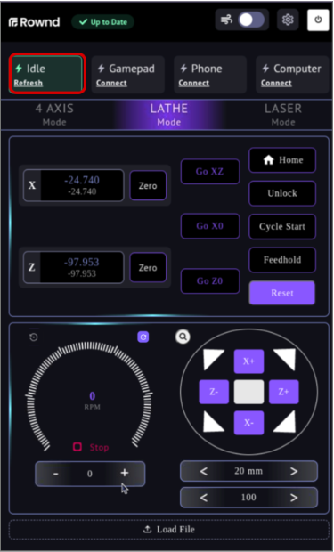
As clearly understood from this example, when the Feedhold button is pressed, the machine immediately pauses its current movement and keeps the remaining part of the command in memory. When the cycle start button is pressed, it resumes and completes the remaining movement to finish the operation.
- Press the “Stop” button to stop the spindle.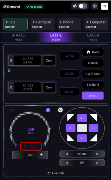
To learn the function of the “Reset” button, set the spindle speed to 250 RPM and click the “Start” button to observe the spindle beginning to rotate.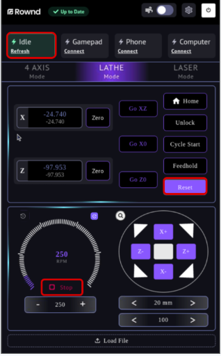
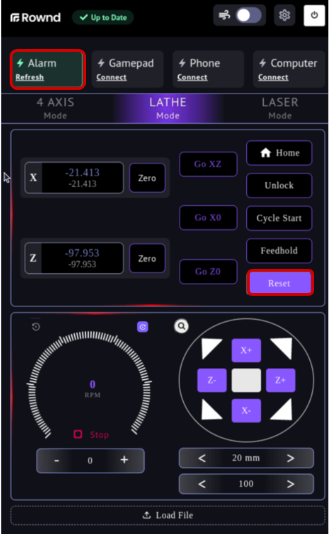
- Set the step size to 10mm and the feed rate to 100 mm/min. Click the “x+” button to move in the +x direction. Before the machine completes the movement, click the “Reset” button. Observe that both the axis movement and the spindle stop, and the machine enters the “Alarm” state.
- To switch from alarm mode to idle mode, click the “Reset” button followed by the “Unlock” button, and observe that your machine enters the “idle” state.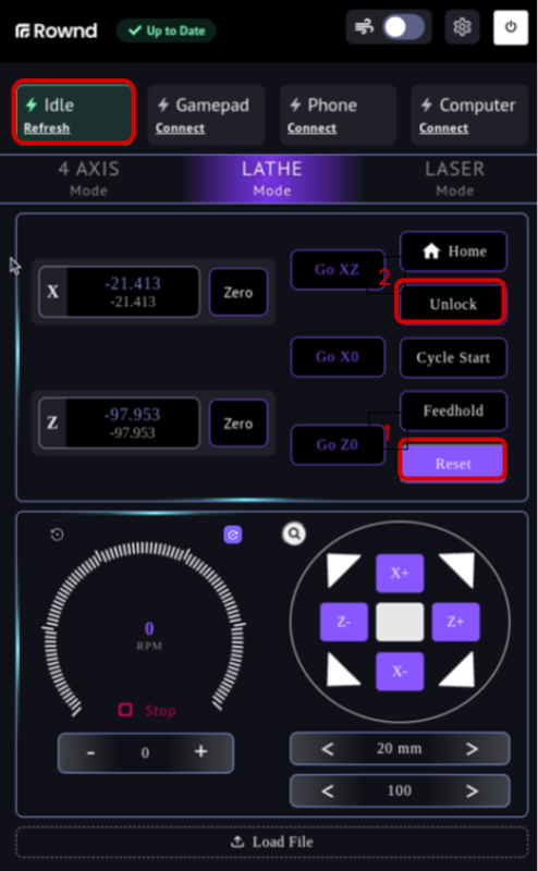
- To learn the function of the protection cover switch, set the spindle speed to 250 RPM and click the “start” button to observe the spindle beginning to rotate.
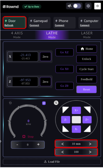
Set the step size to 10mm and the feed rate to 100 mm/min, then click the “x-” button to move in the -x direction. Before the machine completes the movement, open to protection cover.
Observe that the machine stops and machine state switches to the Door state.
To switch from Door state to Idle state, there are two different options: the Reset button and the Cycle Start button. These two methods are explained below.
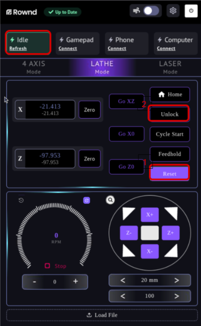
First, make sure the protection cover is closed, then click the “Reset” and “Unlock” button and observe that the machine transitions to the Idle state. Since you have reset the machine, it will not continue the previous movements.
- Set the spindle speed to 250 RPM and click the “start” button to observe the spindle beginning to rotate.
Set the step size to 10mm and the feed rate to 100 mm/min, then click the “x-” button to move in the -x direction. Before the machine completes the movement, open to protection cover. Observe that the machine stops and machine state switches to the Door state.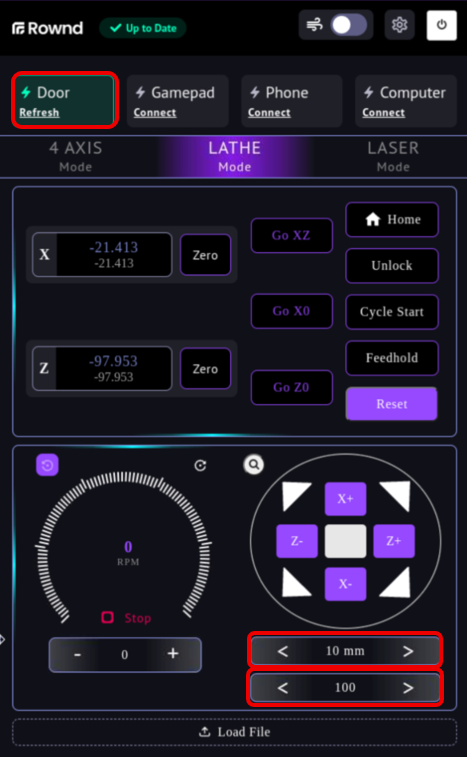
- Secondly, to allow the machine to continue its movement, make sure the protection cover is closed, then click the “Cycle Start” button. Observe that the movements on the X and Z axes continue from where they left off until completed, and that the spindle keeps rotating until you stop it.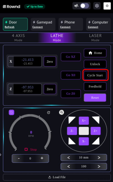
- There are two main buttons to save the machine’s current position: the “ZERO X” and “ZERO Z” buttons.
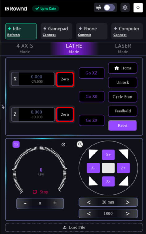
- ZERO X: It is used to save the machine's current position on the x-axis.
In later stages, while machining the part, we will set a reference point and observe that the movements along the x-axis are made relative to the point defined by the “ZERO X” button.
- ZERO Z: It is used to save the current position of the machine on the z-axis.
In later stages, while machining the part, we will set a reference point and observe that the movements along the x-axis are made relative to the point defined by the “ZERO Z” button.
Click the “ZERO X” and “ZERO Z” buttons to set the machine’s current position as zero. Observe that the machine displays the “X” and “Z” values as “0.000.”
- Set the step size to 20mm and the feed rate to 200mm/min, then click the X- and Z- buttons once each. 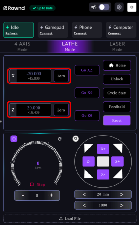
After the movements are completed, observe that “-20.000” is displayed next to the “ZERO X” button and “20.000” is displayed next to the “ZERO Z” button.
- Click the “Go X0” button and observe the machine moving to the “X” position you previously set as zero at maximum speed.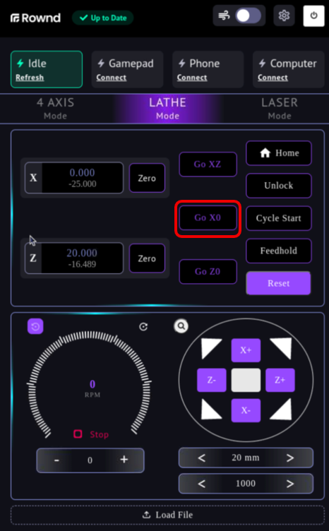
Click the “Go Z0” button and observe the machine moving to the “Z” position you previously set as zero at maximum speed. 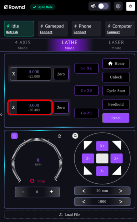
Set the step size to 20mm and the feed rate to 200mm/min, then click the “Z-” and “X+” buttons once each. After the movements are completed, observe that “20.000” is displayed next to the “ZERO X” button and “-20.000” is displayed next to the “ZERO Z” button.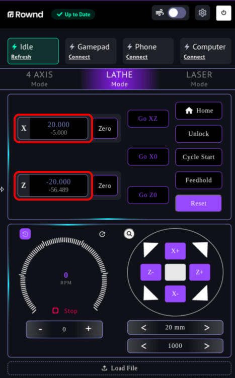
Set the step size to 5mm and the feed rate to 200mm/min, then click the “x-” button to move in the -x direction. Observe that the machine moves 10mm downward. At this stage, notice that “15.000” is displayed next to the “zero x” button and “-20.000” is displayed next to the “zero z” button.
Click the “Go XZ” button on the screen to move the machine to the “X” and “Z” positions you previously set as zero by the shortest possible path.
-The red area marked with “1” is the coordinate you previously set as zero using the “zero X” and “zero Z” buttons.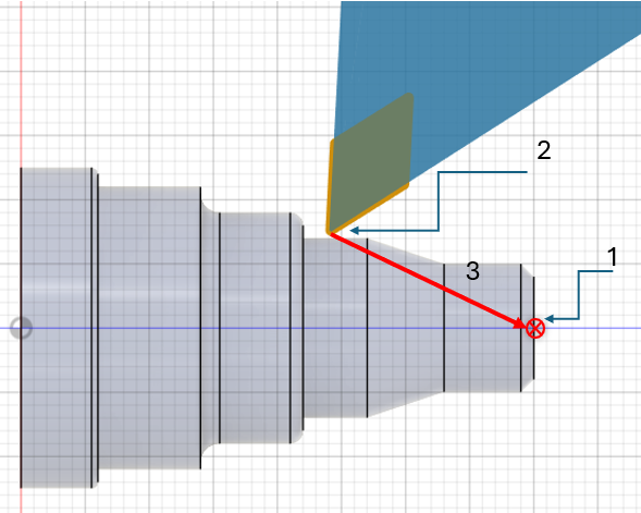
Since the machine tries to move to the zero coordinate via the shortest path, there is a risk that it may collide harshly with the workpiece during this movement.
There is a magnifying glass button on the screen.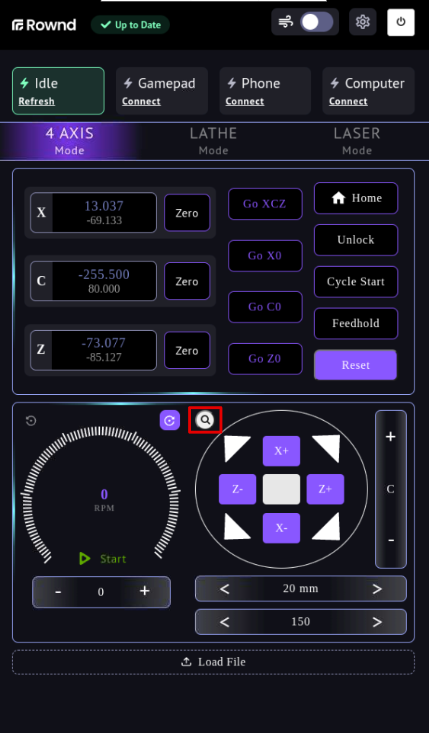
- This button enlarges the axis movement area on the screen, making it more prominent and allowing easier use during manual operations.
Mounting the Workpiece
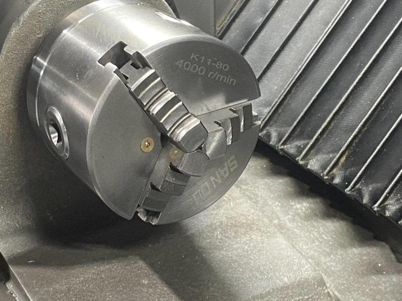
| The minimum and maximum workpiece diameter that can be mounted on the chuck with standard jaws is 2 to 30 mm. | 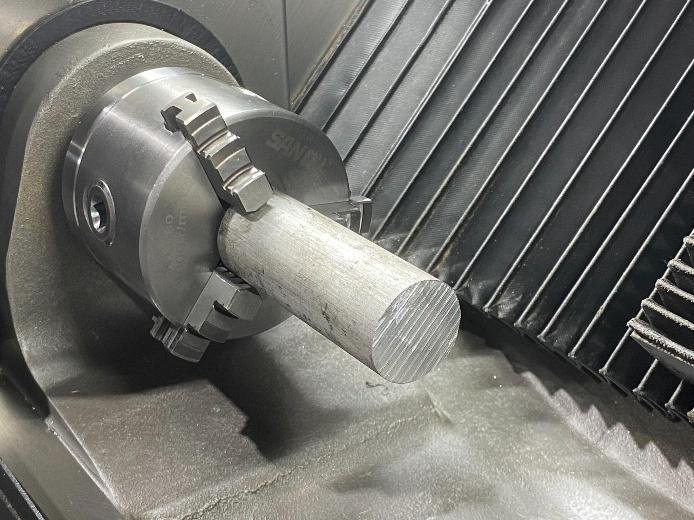 |
|---|---|
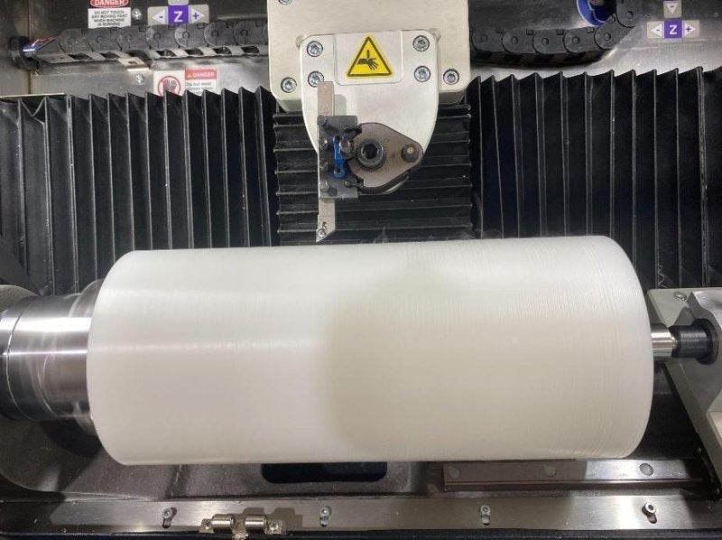
| The minimum and maximum workpiece diameters that can be mounted on the chuck using reverse jaws, as shown in the image below, are 30 mm and 80 mm, respectively. | 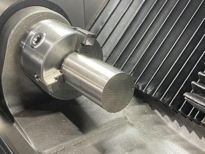 |
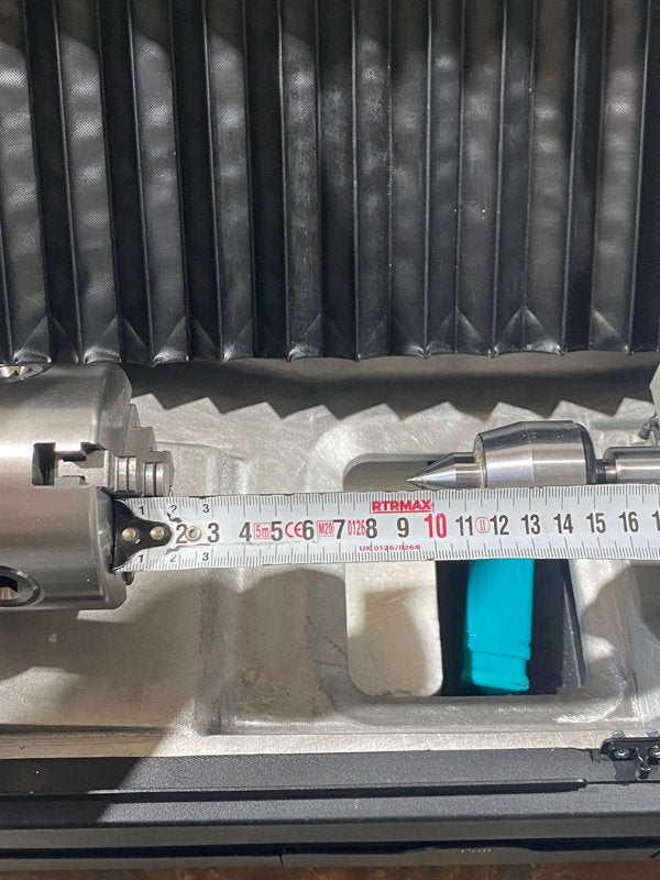
The length of the workpiece mounted using a tailstock can be between 92mm and 273mm. The maximum travel distance of the tailstock is 190 mm.
To mount your workpiece on the chuck, follow the steps below:
1. First, loosen the chuck jaws using the chuck key.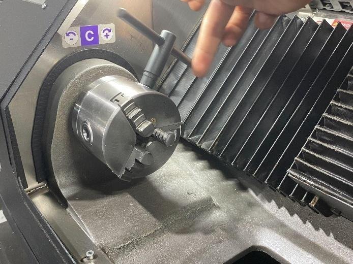
2. Place the demo part into the chuck as shown in the image below.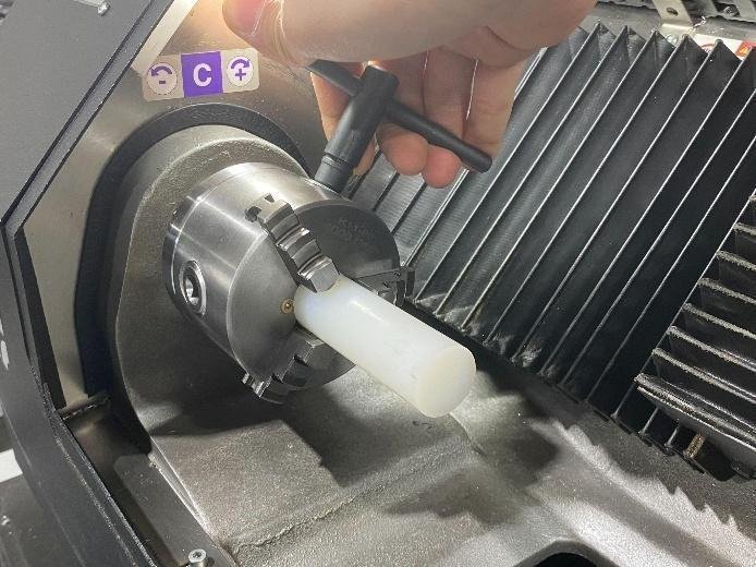
3. After placing the material, ensure that the chuck jaws are tightened securely.
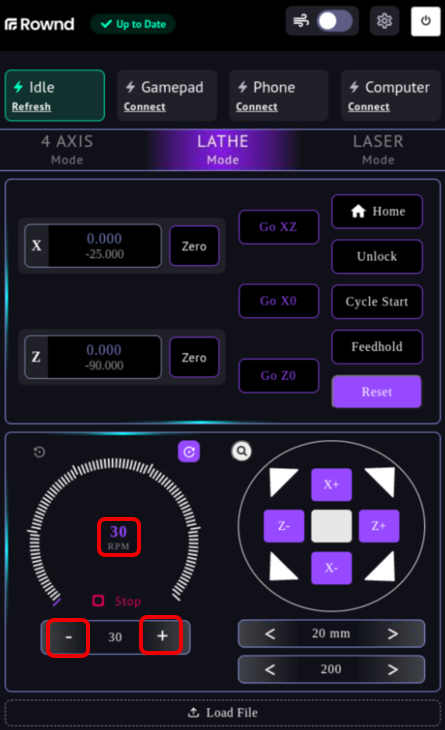
4. First, set the machine to Lathe mode and run the spindle at 30 RPM.
5. Observe the spindle’s rotation and ensure that the material placed in the chuck is not wobbling. If the material is wobbling, stop the spindle’s rotation and correct the wobble of the part.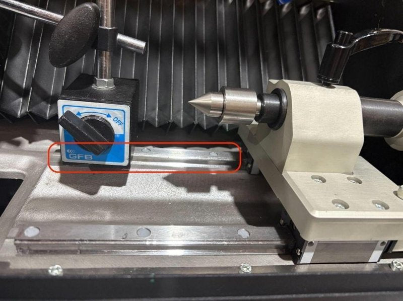
If the diameter of your workpiece is between 30 and 80 mm, you need to attach the reversed jaws to your chuck. To do this, follow the steps below: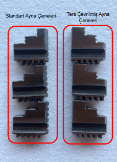
1. To change the chuck jaws, first, remove the installed jaws. To do this, loosen the chuck until the jaws come out.
2. Next, find the number 1 written on the inner part of the chuck.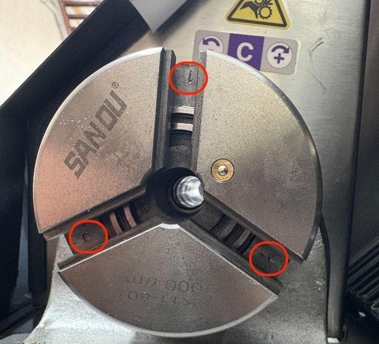
3. Find the number 1 jaw from the jaw set you want to install on the chuck.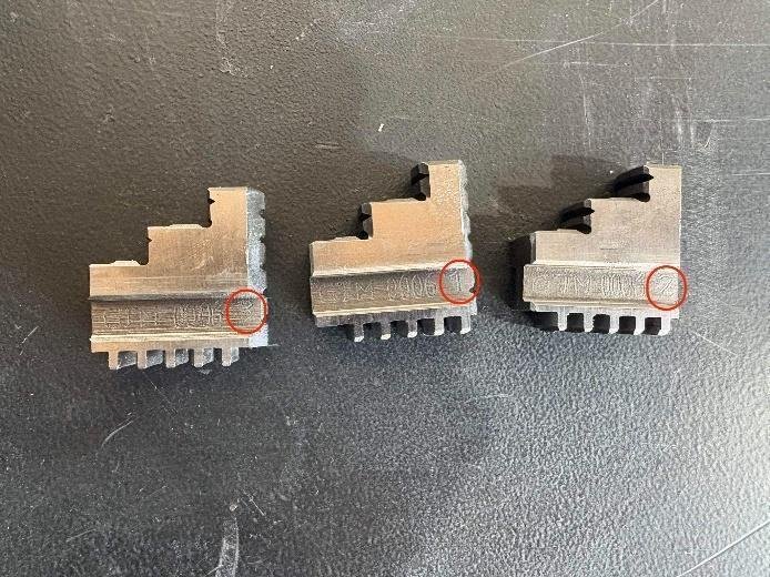
4. Loosen the chuck using the chuck key to bring it to the position shown in the photo.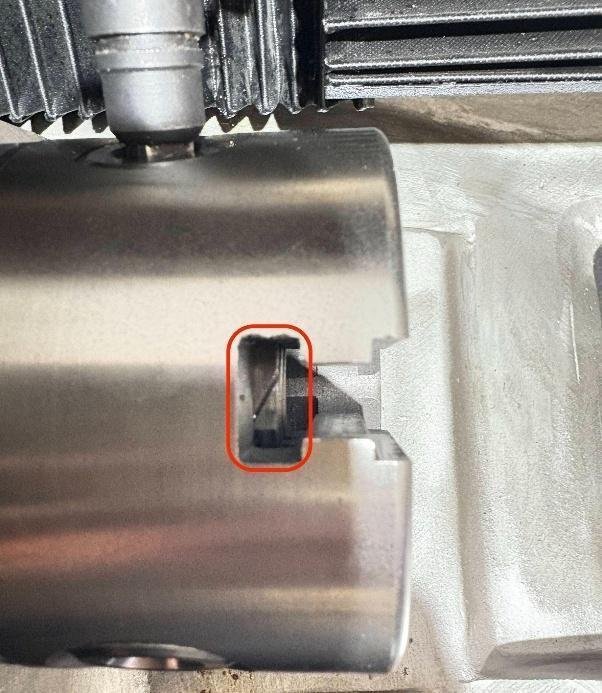
5. After ensuring that the chuck is in the shown position, loosen it one more turn and observe that the screw lead has disappeared.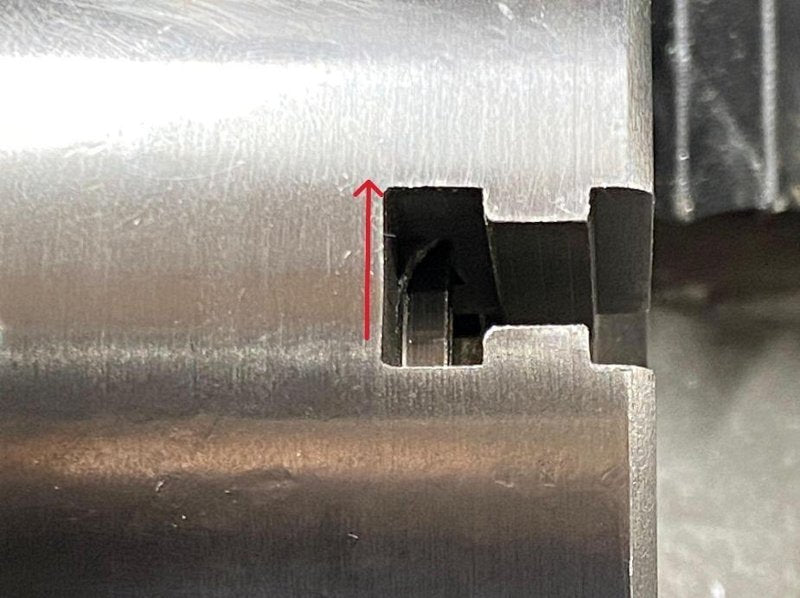
6. Place the number 1 jaw.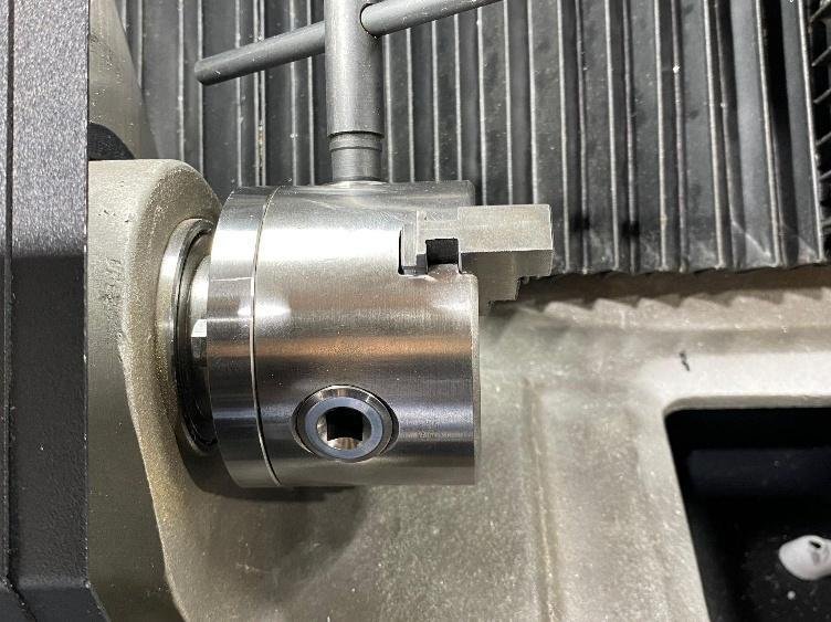
7. Tighten the chuck two turns.
8. Make sure that when you pull the jaw upward by hand, it does not move.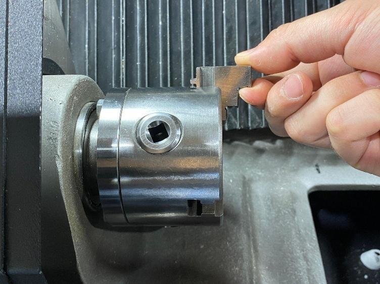
9. To install the number 2 chuck jaw, manually rotate the chuck and find the number 2 marking inside the chuck.
10. Then, tighten the chuck to bring it to the position shown in the photo.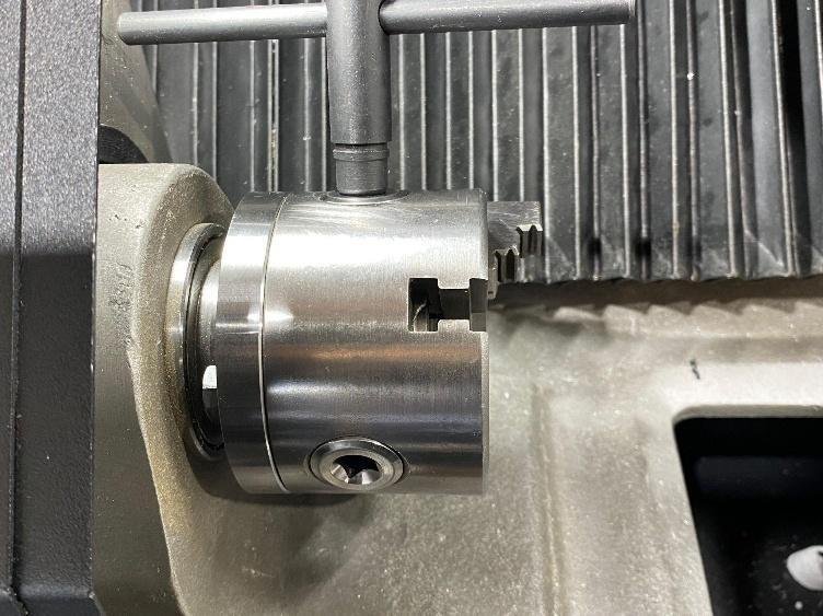
11. After ensuring that the chuck is in the shown position, loosen it one more turn, place the number 2 jaw, and then tighten the chuck two turns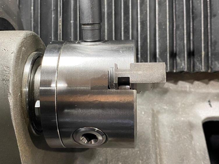
12. To install the number 3 chuck jaw, manually rotate the chuck and find the number 3 marking inside the chuck.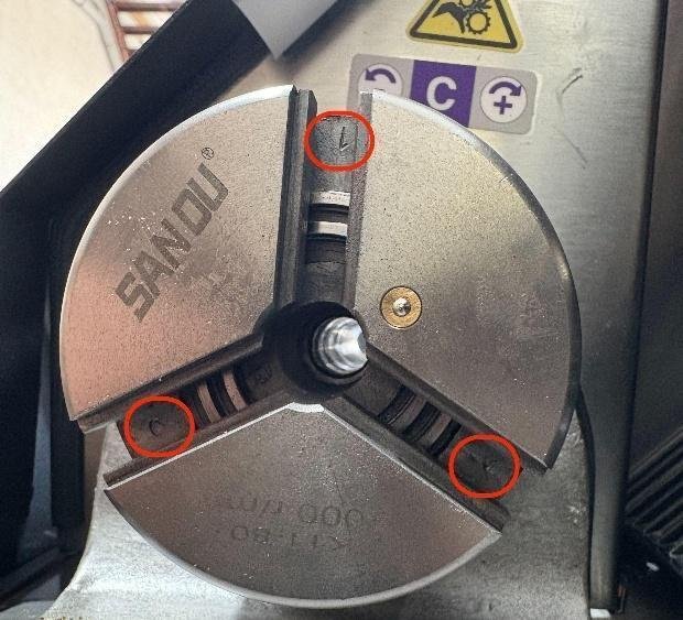
13.. Then, tighten the chuck to bring it to the position shown in the picture.
14. After ensuring that the chuck is in the shown position, loosen it one more turn, place the number 3 jaw, and then tighten the chuck two turns.
15. After installing all the jaws, fully tighten the chuck and ensure that the jaws meet at the center of the chuck. If they do not align properly, restart the process from the beginning.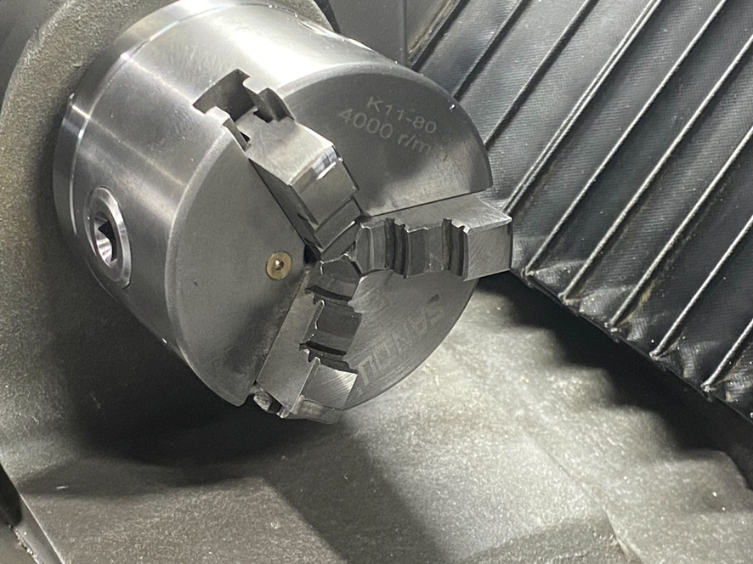
To mount the workpiece using the tailstock, follow the steps below:
1) Place your workpiece to the chuck.
2) Loosen the tailstock stopper lever and bring the tailstock up to the workpiece.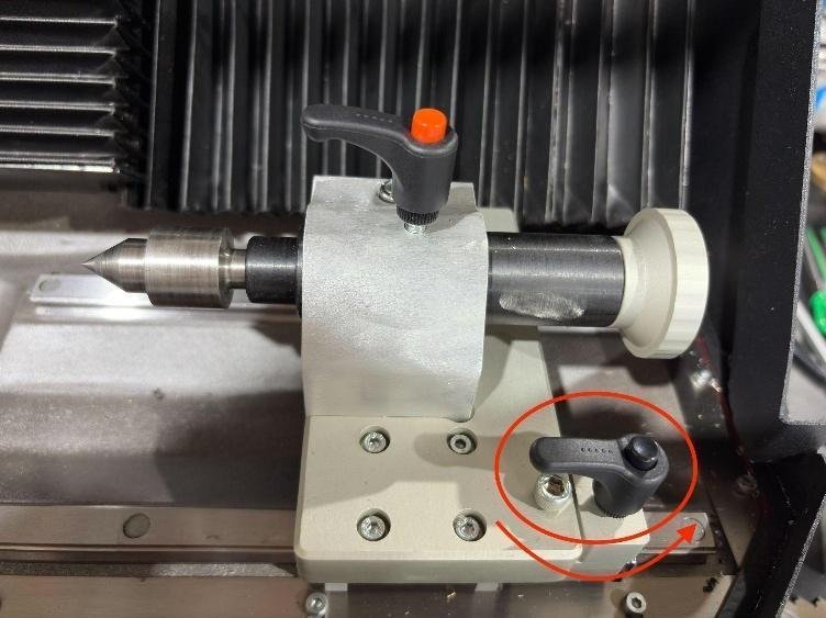
3) If the tailstock length is insufficient
- loosen the tailstock clamping lever.
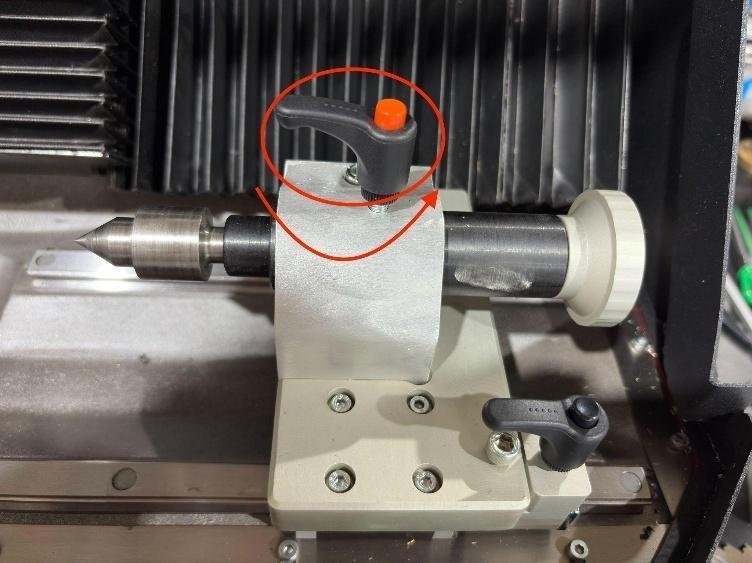
- Turn the tailstock handwheel to extend the length of the tailstock.
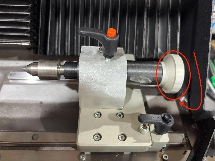
- Tighten the tailstock locking lever when the tailstock length touches the workpiece.


4) After touching the tailstock to the workpiece, tighten the tailstock stopper lever.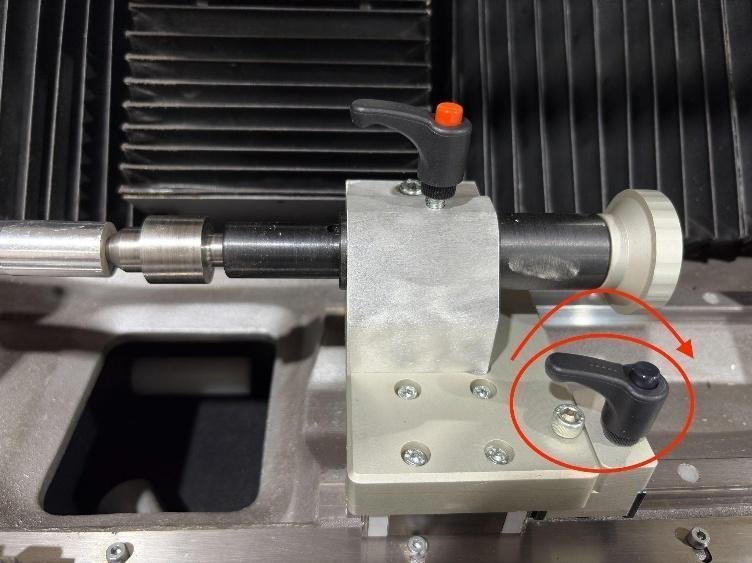
7. Lathe Mode Operations
Lathe Mode
| The Lathe mode of your machine is used for turning operations when the QCTP (tool holder) add-on is attached. Below is a step-by-step explanation of how to work on a part in Lathe mode. | 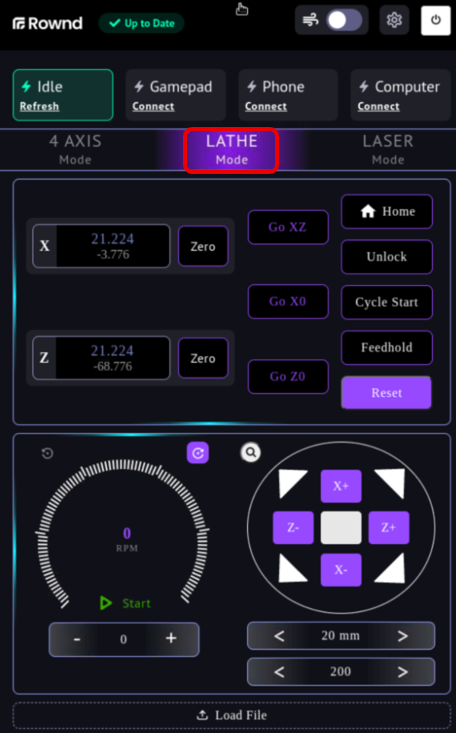 |
|---|
Pre-Check
1. Ensure all screws are tight.
2. Ensure that there are no frayed or broken parts.
3. Ensure that QCTP add-on is securely tightened.
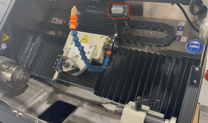
4. Ensure that the add-on connector cover is properly installed.
5. Ensure that the tool holder securely grips the cutting tool.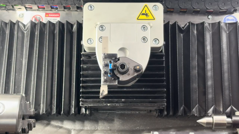
6. Ensure that the Warm-up program was applied after opening the machine.
Lathe Interface
QCTP
QTCP is a tool holder. QCTP offers different angle and height adjustments. Additionally, thanks to the quick tool change feature, you can quickly swap multiple cutters used in your project. In the QCTP set we have provided, there are three four-sided grooved QCTP tool holders and one V-grooved QCTP tool holder.
The four-sided grooved holders are designed for clamping standard rectangular or square tools or cutters, while the V-grooved holder is intended for clamping round-section tools or cutters.

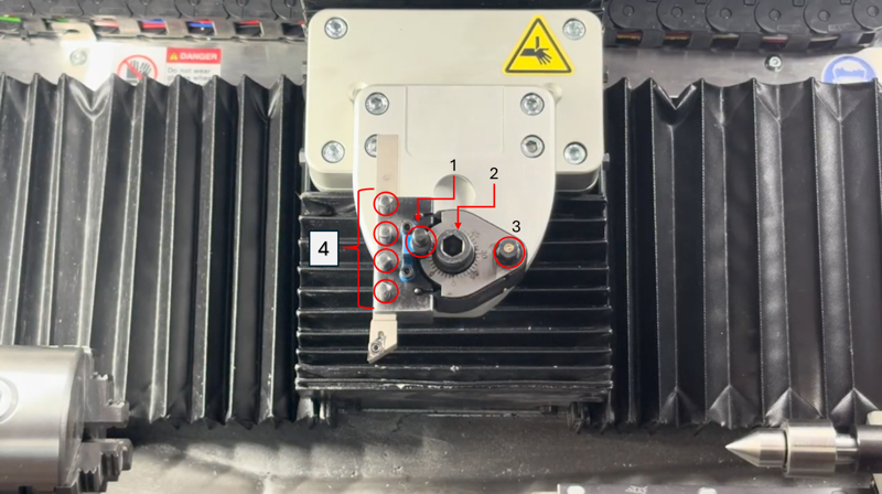
- QCTP height adjustment screw: This screw is used to adjust the cutting-edge height of the tool on the QCTP relative to the center of the workpiece.
- QCTP fastening screw: It is used to fasten the QCTP body to the machine. There is a nut at the bottom of the part to tighten this screw.
- QCTP tightening-loosening screw: The QCTP loosening screw allows the tool holder to be removed and installed by loosening it.
- QCTP cutter clamping screws: The QCTP cutter clamping screws secure the cutter tool to the tool holder.
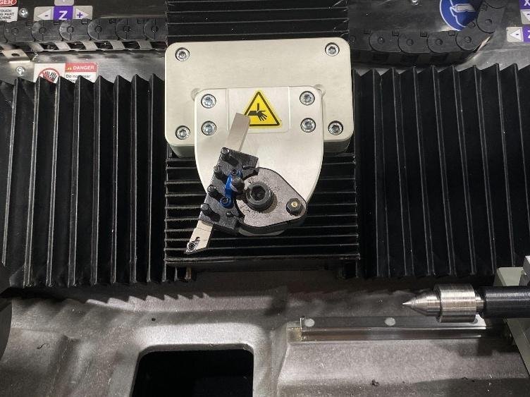
- To adjust the angle of the QCTP Tool Holder, attach the QCTP wrench and turn it counterclockwise.
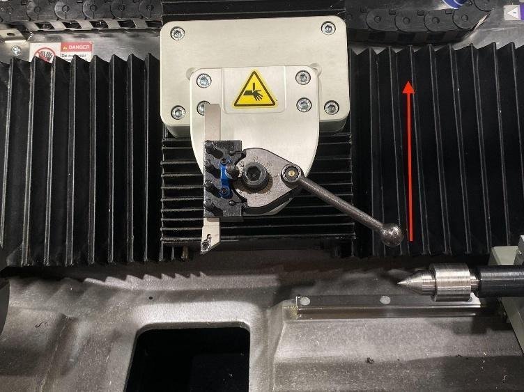
- To change the angle of your cutter tool, pull the QCTP holder upward to remove it.
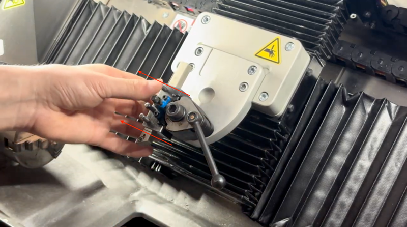
- You can rotate the QCTP and reattach the QCTP holder at your desired angle.
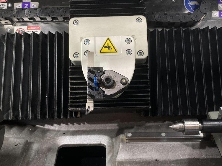
- Turn the QCTP wrench clockwise to tighten the tool holder.
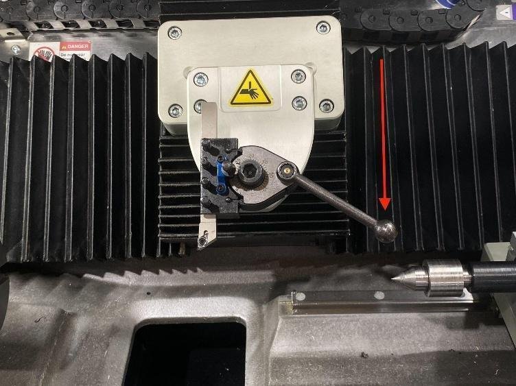
- Make sure to attach the QCTP vertically using the methods you have learned up to this step for general operations.
QCTP Calibration
The following steps explain procedures such as removing and installing the cutter and removing and installing the QCTP holder.
- Secure the magnetic base of the dial indicator to the tailstock rail.
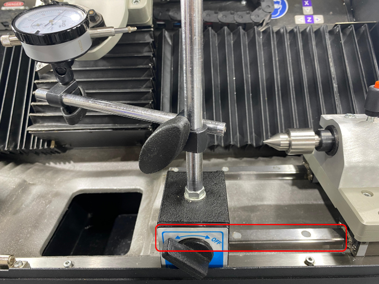
- Using the axis movements, move the machine to the appropriate position and ensure that the dial indicator touches the flat surface of your cutter.

- Loosen the QCTP fastening screw slightly with an 8mm Allen wrench. If necessary, use a 17mm wrench to hold the nut located at the bottom where the QCTP is attached, and perform the tightening/loosening together.
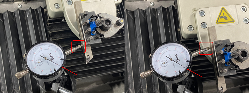
- Move the machine along the X-axis and read the runout on the dial indicator.
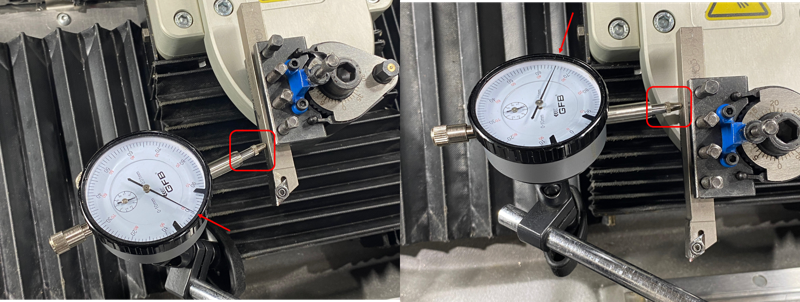
- Using the reading from the dial indicator, adjust the cutter to a perfectly vertical position, then tighten the QCTP fastening screw with an 8mm Allen wrench to complete the procedure.

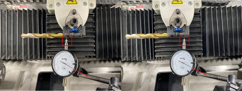
- Attach the workpiece to the chuck and make sure it is securely fixed to the chuck and does not wobble.
- Move the workpiece along the X-axis in the “-x” direction to a position farther from the face of the workpiece, lowering it until it aligns with the position shown below.
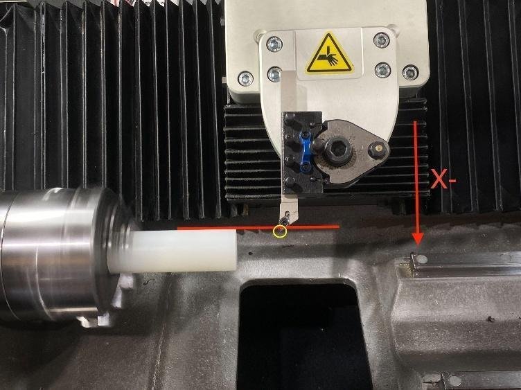
- Then, stop the spindle rotation and mark the face of the workpiece with a visible-colored marker.
- Set the spindle speed to 2000 RPM. To approach the workpiece in the -Z direction, set the step size to 0.5 mm and the feed rate to 200 mm/min, then click the “Z-” button to move toward the face of the workpiece. Continue the movement until the cutting tool touches the workpiece.
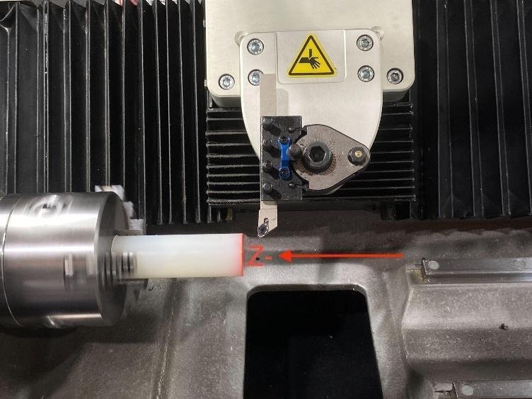
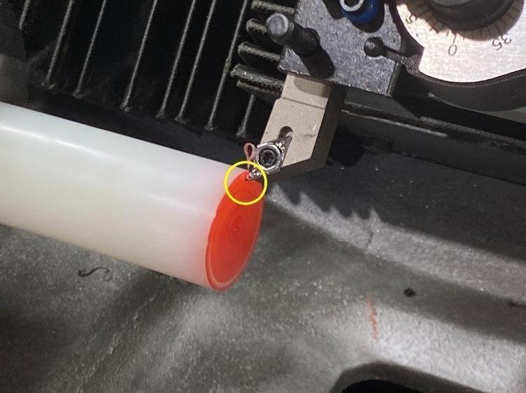
- After the tip of the cutting tool touches the workpiece, move the tool upward along the X-axis until it passes over the top surface of the workpiece and clears the part.
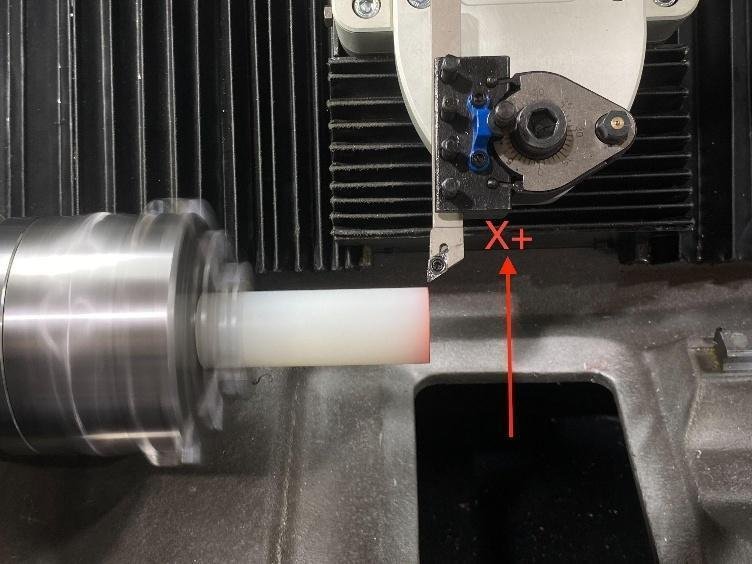
- Set the step size to 0.3 mm and the feed rate to 200 mm/min. Click the “Z-” button once to move in the -Z direction. Then, move in the -X direction until the cutting tool touches the workpiece.
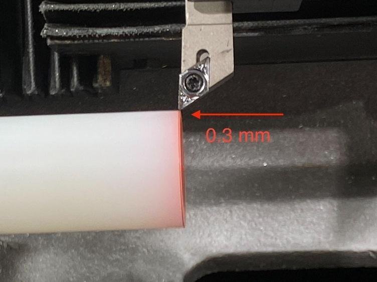
- Set the step size to 1 mm and the feed rate to 200 mm/min. Click the “X-” button to move step by step toward the center of the workpiece.
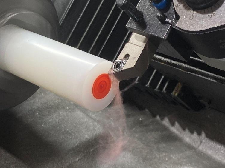
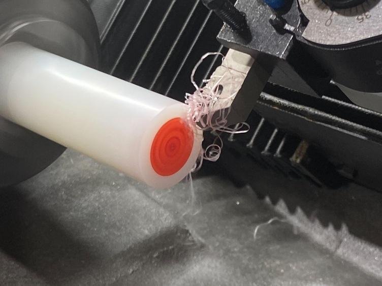
- Continue the operation until a small part remains at the center of the workpiece.Note: If the cutter height is not correct, the remaining material at the center will not align with the center of the cutter. In the first image below, the cutter is positioned above the center, while in the second image, the cutter is positioned below the center as examples.
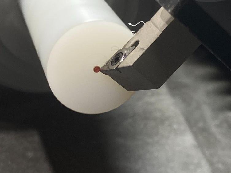
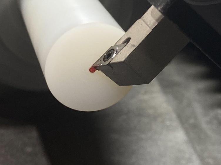
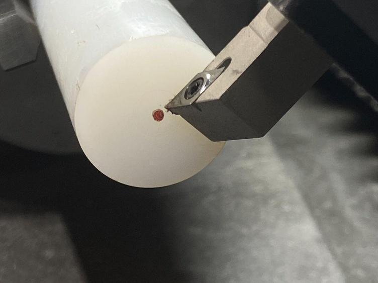
- After confirming that the cutter is not centered, without performing any further operation, set the step size to 1 mm and the feed rate to 200 mm/min. Then, click the “x+” button once to move the cutter out of the unprocessed region at the center.
- Click the “Stop” button to stop the chuck.
- To adjust the cutter height, you need to loosen the QCTP holder. Loosen the QCTP tightening-loosening screw using the QCTP wrench and Make sure the QCTP holder is loose by checking it manually with your hand
- Loosen the locknut on the QCTP height adjustment screw located.
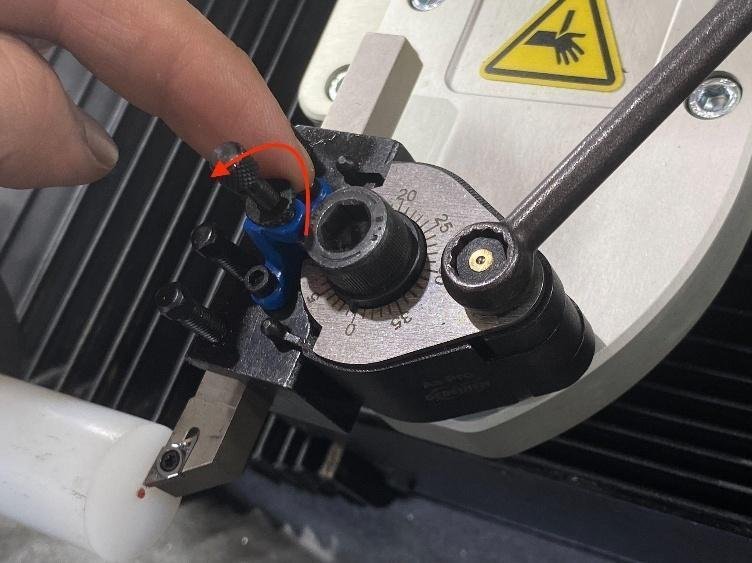
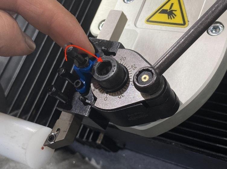
- Using the QCTP height adjustment screw, align your cutter to the center of the protrusion.

- To prevent the adjusted height from shifting, firmly tighten the lock nut on the QCTP height adjustment screw.
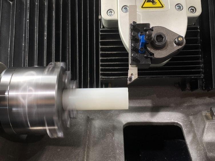
- To verify whether the cutter height is correctly adjusted, set the spindle speed to 2000 RPM and move in the +X direction until it reaches the surface of the workpiece.
- Set the step size to 0.2 mm and the feed rate to 200 mm/min, then click the “z-” button once to move in the -Z direction.
- Set the step size to 1 mm and the feed rate to 200 mm/min, then move downward along the -X axis until the center protrusion on the workpiece disappears.
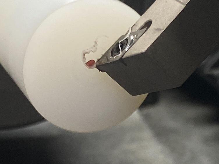
- Make sure the cutter height is aligned with the center of the workpiece.
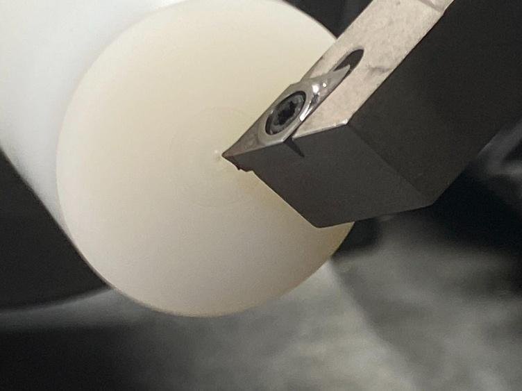
Workpiece Zero Setting
To zeroing your workpiece in lathe mode, follow the steps below:
- Run the spindle at 2000 RPM.
- Use the axis control buttons on the touchscreen to bring the cutting tool closer to the material.
- Move downward along the X-axis in the “-x” direction to a position farther away from the face of the workpiece.
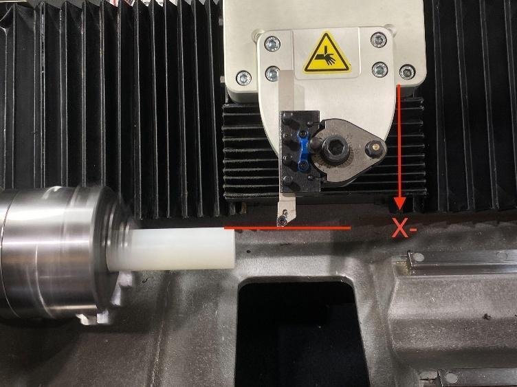
- Set the step size to 0.5 mm and the feed rate to 200 mm/min to approach the workpiece in the -Z direction. Then click the “Z-” button to move closer to the face of the workpiece.
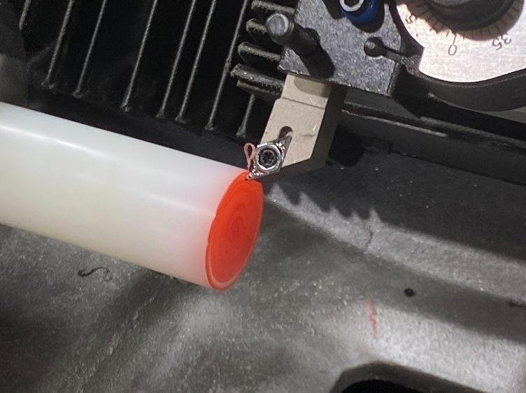
- After the tip of the cutting tool touches the workpiece, move the tool upward along the X-axis until it passes over the top surface of the workpiece and clears the part.
- Set the step size to 0.3 mm and the feed rate to 200 mm/min. Click the “Z-” button once to move in the -Z direction.
- Set the step size to 1 mm and the feed rate to 200 mm/min. Click the “X-” button to move step by step toward the center of the workpiece. Continue until there is no visible part at the center of the workpiece.
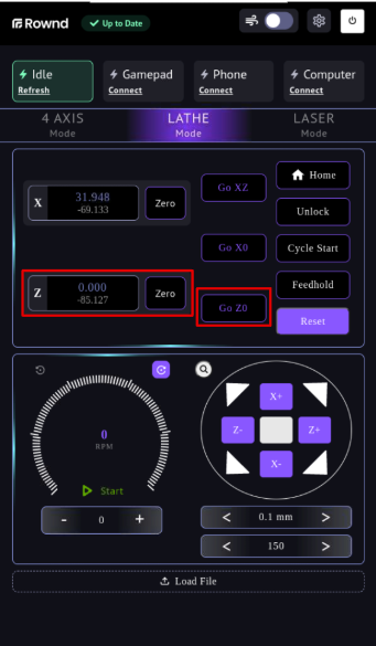
- Click the “Zero Z” button to zero the Z axis at this position (center of the part).
- Move upward along the X-axis until the tool passes beyond the surface level of the part and continue moving farther away from the part’s diameter as shown in the image.
- Set the step size to 0.05 mm and the feed rate to 100 mm/min. Then, move gradually along the X axis in the -X direction, step by step, and continue until the cutting tool touches the top surface of the workpiece.

- After the cutting tool first touches the workpiece, set the step size to 0.2 mm and the feed rate to 200 mm/min. Then, click the “x-” button once to move in the -X axis direction.
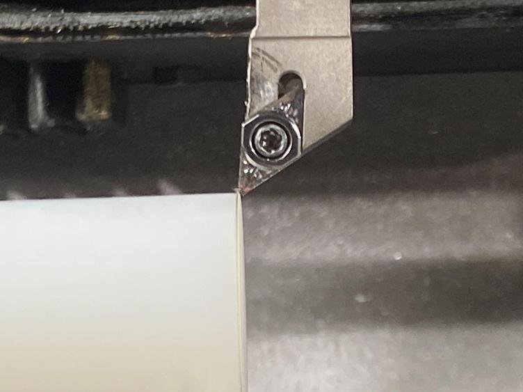
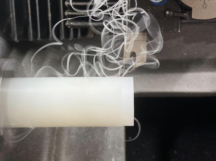
- Set the step size to 10 mm and keep the feed rate unchanged. Press the “z-” button to move in the -Z direction while cutting the material. Then, press the “z+” button to return to the initial point where material removal started.
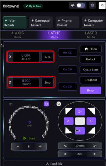
- Set the X coordinate by clicking the 'zero x' button.

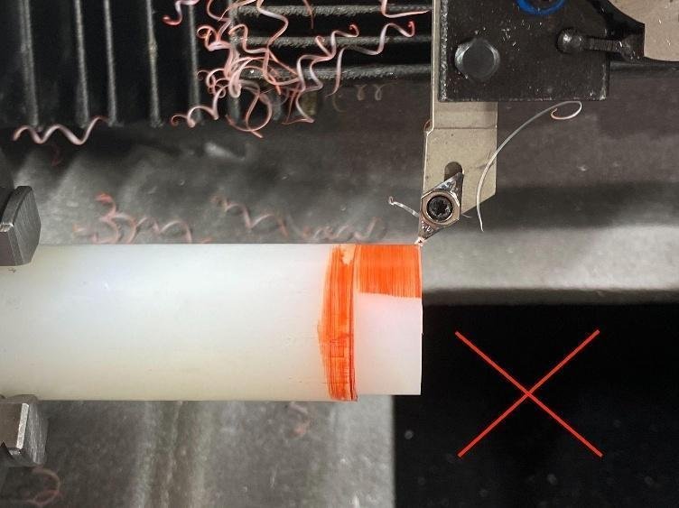
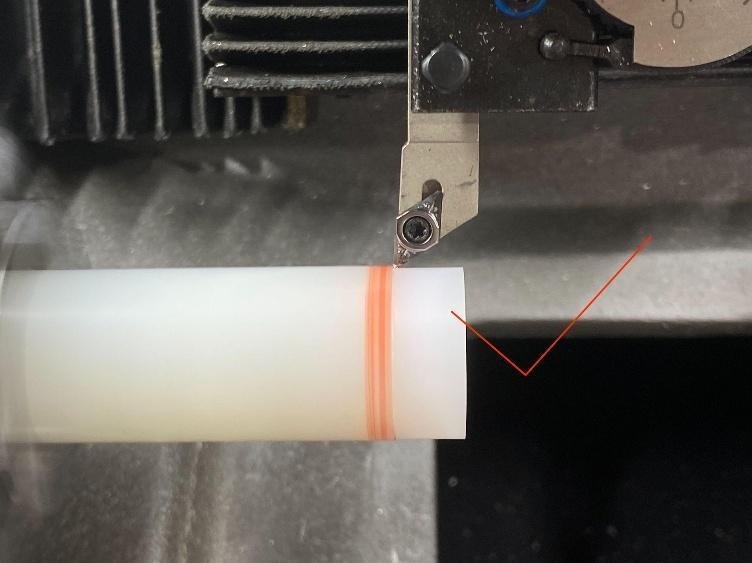
- To stop the spindle, press the “Stop” button.
- Measure the outer diameter of the workpiece using a caliper.
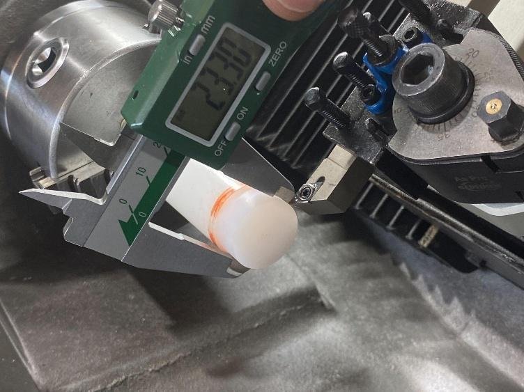
- Calculate half of the measured value. This value will be your radius and represents the distance from the center of the workpiece to the final machined surface. For example, in the image above, the diameter is 23.30 mm. Therefore, the workpiece zero is 23.30 / 2 = 11.65 mm distance from the temporary zero.
- Set the step size to 10 mm and the feed rate to 1000 mm/min. Then, click the “z+” button to move Z+ direction.
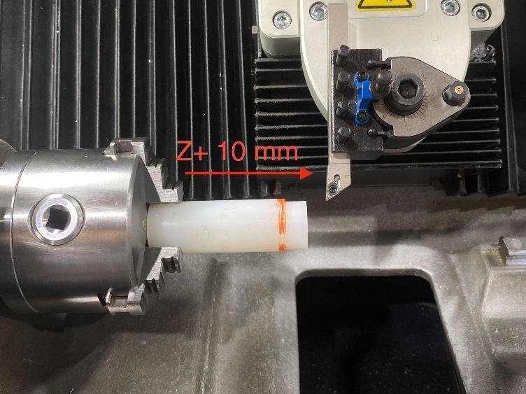
- Move the X axis until you reach the value obtained in Step 16 (11.65 mm).
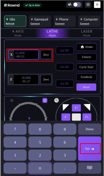
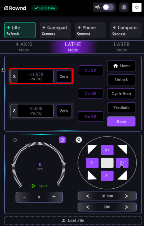
- At this coordinate, which is the exact center of the workpiece, set the machine zero using the “Zero X0” button.
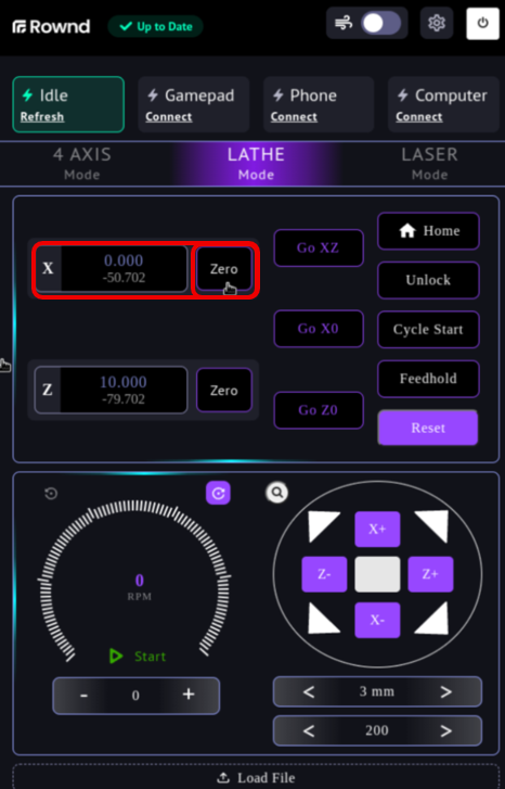
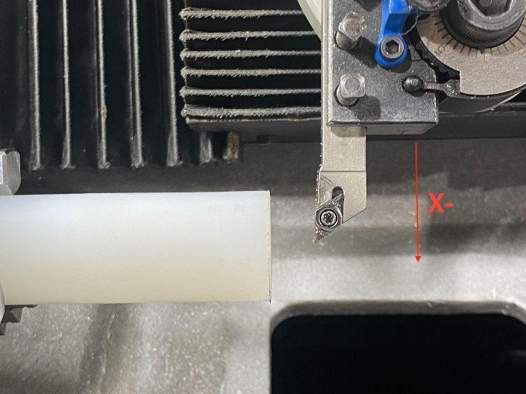
Running the G-Code File
To run the G-Code file, follow the steps below:
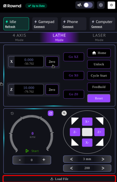
- Click the Load File button on the screen.
2. From the opened window, select Desktop and open the Demo Part folder.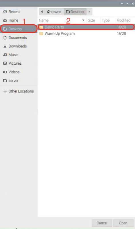
3. Enter the Lathe folder.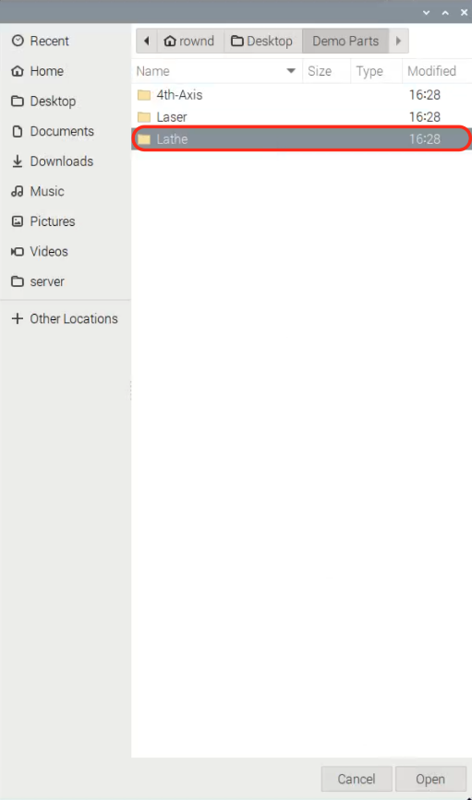
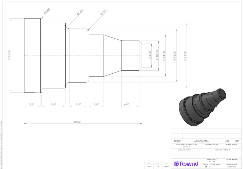
4. Select the file named ‘Lathe_Demo.NC’ and click ‘Open’.
5. At this stage, the G-Code can be run directly by clicking the ‘Run’ button, or it can be reviewed first by clicking the ‘Preview’ button and then executed afterward.
Read From USB Memory
| 1. If the G-Code file on a USB flash drive, insert your USB flash drive into the machine’s USB port. Note: You can use a USB hub to connect multiple USB devices such as a mouse and USB flash drive to your machine. |
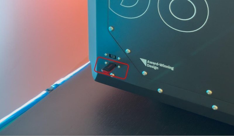 |
|---|---|
| 2. Click the "Load File" button. |  |
3. Select your USB flash drive.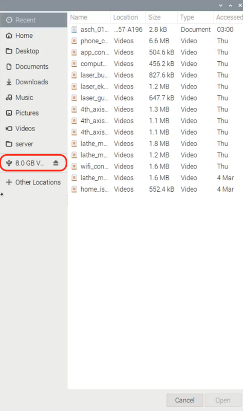
4. Select the G-Code file to run and click the Open button.
| 5. The G-code file can be run by clicking the Run button, or it can be reviewed before running by clicking the Preview button. | 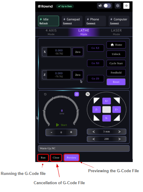 |
|---|
| Below is a screen shot of the preview screen opened by pressing the Preview button. | 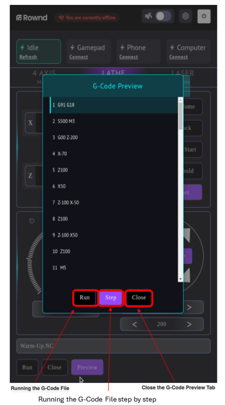 |
|---|
| After pressing the Run button, the information displayed on the screen is as follows. The device can be paused by pressing the Pause button. | 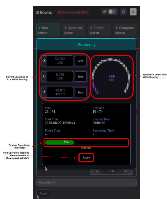 |
|---|
| After pressing the Pause button, the following screen appears. Pressing the Resume button will continue the operation from where it was paused, while pressing the Skip button will stop the operation completely. | 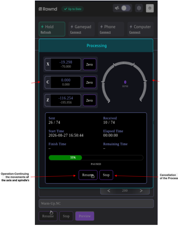 |
|---|
After the machine completes its operations, you are now ready to remove the processed material.
1.First, open the protection cover and remove the part from the chuck.
2.Clean your processed material using a brush.
3.Do not use any liquid substances to clean the material.
4.Clean out any chips that may have accumulated between the bellows.
5.Sweep all visible chips inside the machine into the chip bin.
8. 4th-Axis Rotary Mode
4th-axis Mode
Your machine’s 4th axis mode is used to perform live tool operations when the live tool add-on is installed.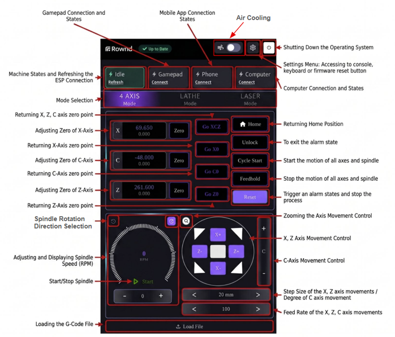
Live Tool Motor Installation & First Experience
At this stage, the installation process and initial checks of the live tool attachment to be used in 4-axis mode are demonstrated.
| Using a 5 mm Allen key, place the 4 bolts into the add-on slot and tighten them gradually in a crisscross pattern. Ensure all screws are tight. Ensure that the slides are in good condition without any nicks or damage. Make sure there is no visible damage on the live tool motor cables. |
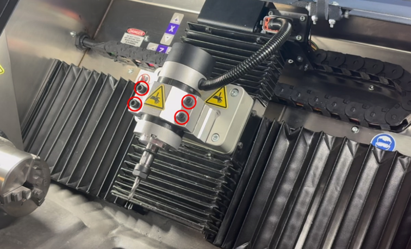 |
|---|
- Ensure that there are no frayed or broken parts.
- Ensure that the live tool connector is properly connected to the add-on connector.
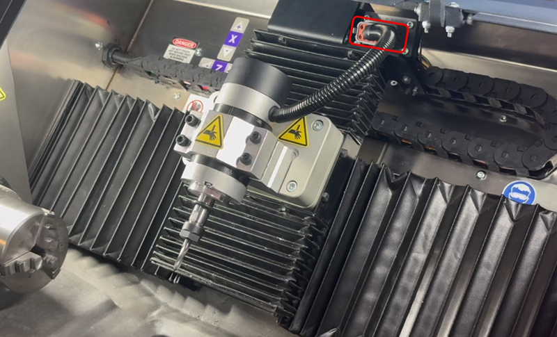
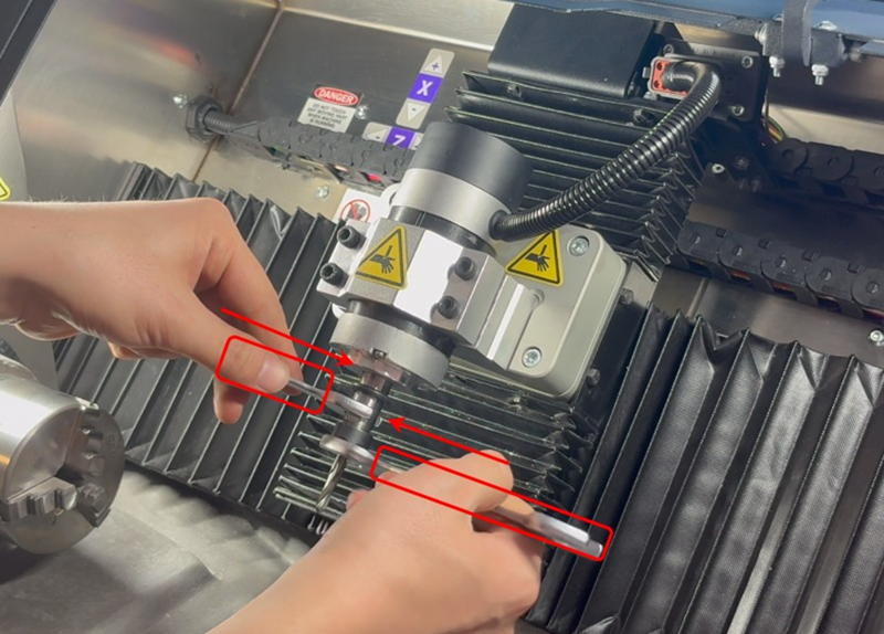
- Loosen the ER11 nut using M14 and M17 wrenches and remove the nut by turning it; it contains the ER11-3 mm collet inside.

- If you wish to use a different collet, gently press the collet towards the collet holder and perform the replacement.
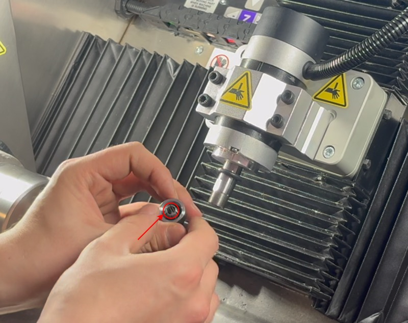
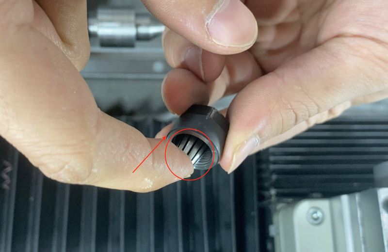
- To reinstall the ER11 collet, place it into the nut and push it down.
- Lightly attach the nut containing the ER11 collet to the spindle and insert the rear part of the cutting tool into the collet.
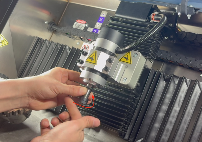
- Tighten the ER11 nut using M14 and M17 wrenches.
- Check the machine's state, and if it is not in the Idle state, ensure that it switches to the Idle state.
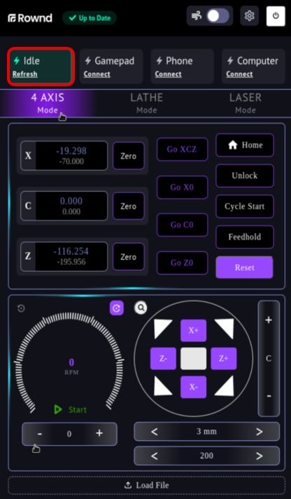
- Click the 4-AXIS button on the screen to switch to 4th AXIS mode. Use the RPM bar to set the speed to 5200 RPM, then click the Start button. Make sure that the spindle is rotating clockwise. Note: If the machine state is not Idle, the device will not allow a mode change.
- Press the “Stop” button to stop the spindle rotation.
- Use the direction buttons at the top-left corner of the RPM bar to select counterclockwise rotation.

- Use the RPM bar to set the speed to 5200 RPM, then click the Start button, make sure that the spindle is rotating counterclockwise.
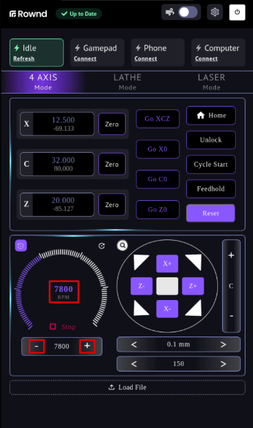
- Use the “+” and “-” buttons located below the RPM bar to increase the live tool speed up to 12,000 RPM, then decrease it to 5,100 RPM.Note: You can perform this operation either by clicking the “+” and “-” buttons one by one or by holding them down.
- Press the “Stop” button to stop the spindle rotation.
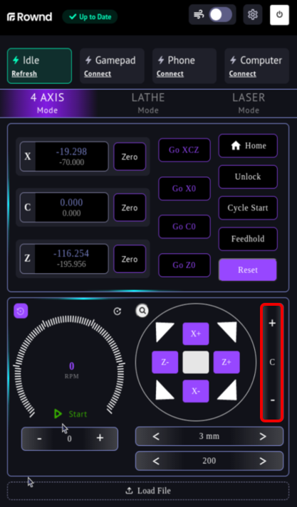


- Set the step size to 100 and the feed rate to 1000 RPM, then press the “+” C button and observe the chuck rotating 100 degrees clockwise.Note: The step size value represents movement in millimeters on the X and Z axes, while on the C axis, it represents rotation in degrees.
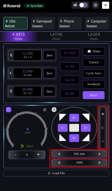
In addition to the zeroing and go-to-zero operations performed on the X and Z axes, follow the steps below to learn how to zero and return to zero on the C axis.
- Click the “Home” button to make the machine move to its home (zero) positions.
- Press the “Z-” button to move 150 mm to the left on the Z axis.
- Press the “X-” button to move 50 mm down on the X axis.
- In this position, click the “Zero X,” “Zero Z,” and “Zero C” buttons to zero all three axes.
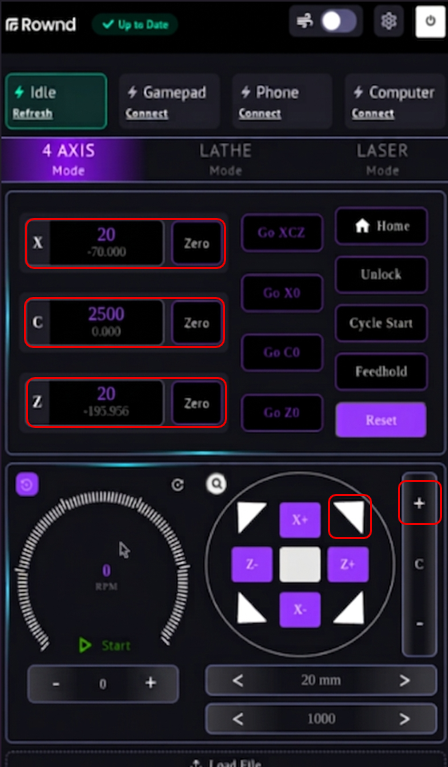
- Set the step size to 20 mm and the feed rate to 1000 mm/min, then click the top-right diagonal direction button. Observe the machine moving at a 45° angle towards the top-right.
- Set the step size to 180 mm and the feed rate to 1000 mm/min, then click the "+" C button once. As a result, the chuck will rotate 2500°.
- At the end of these operations, observe that the X axis is at 20 mm, the Z axis is at 20 mm, and the C axis position value is 2500°, as shown in the image below.
- Click the “Go XCZ” button and observe that all three axes move to the reference coordinate we defined as zero in item 23.Note: The “Go X”, “Go C”, and “Go Z” buttons are used to perform the zeroing operation individually for each axis, depending on which axis users want to prioritize.
- Set the step size to 20 mm and the feed rate to 200 mm/min, run the spindle at 5200 RPM, and move in the “-X” direction. Before the movement is complete, click the “Feed Hold” button and observe that both the axis movement and the spindle stop.
- Click the “Cycle Start” button and observe that the axis movement continues and the spindle keeps rotating at the same speed.Note: The spindle will not stop automatically when the axis movement is completed.
- To test the function of the door switch, set the spindle to 5200 RPM and click the “Start” button to observe the spindle starting to rotate.
- Set the step size to 10 mm and the feed rate to 100 mm/min, then click the “X-” button. Before the machine completes its movement, open the protection cover. Observe that the machine stops and switches to the “Door” state.
- Close the cover, press the “Reset” and then the “Unlock” buttons in sequence, and observe that the machine state is Idle. Notice that because the “Reset” button was pressed, the machine does not resume movement.
- Set the speed to 5200 RPM, then click the Start button.
- Set the step size to 10 mm and the feed rate to 100 mm/min, run the spindle at 5200 RPM, and move in the “-X” direction. Before the machine completes its movement, open the protection cover. Observe that the machine stops and switches to the “Door” state.
- Close the cover, click the “Cycle Start” button, and observe that the axis movement continues and the spindle keeps rotating.
4th Axis Live Tool Calibration
This section explains the steps you need to follow to check the linearity of the live tool. By following the steps below in order, you can perform the linearity calibration of the cutting tool.
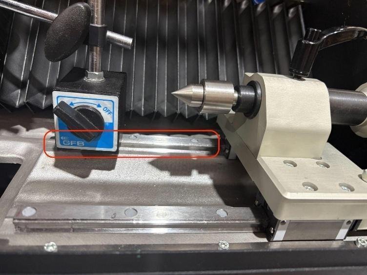
- Place the dial indicator on the lathe’s guideways.
- Adjust the tip of the dial indicator so that it contacts the spindle surface.
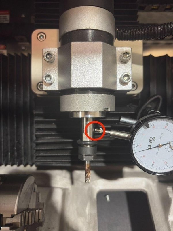
- Move the X axis 5 mm in both positive and negative directions with a step size of 5 mm and a feed rate of 200. According to the value shown on the dial indicator, loosen the screws holding the live tool motor, adjust its linearity, and then tighten the screws again.
Settings
Axis Mode (Diameter / Radius Mode)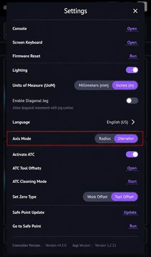
The Diameter-Radius Mode determines whether the machine's movement is based on the part's diameter or radius, according to the command given on the X-axis.
When the machine is in Radius mode, the indicator on the screen shows the letter X. When the machine is in Diameter mode, it shows the letter D.
• Radius mode: The machine moves by the exact amount given in the command. For example, when a 10 mm movement is commanded on the X-axis, the cutting tool moves 10 mm. As a result, a total of 20 mm is removed from the diameter of the part.
• Diameter mode: The given command is automatically adjusted according to the movement on the diameter of the part. For example, when a 10 mm movement is commanded on the X-axis, the cutting tool moves 5 mm. As a result, 10 mm is removed from the diameter of the part.
The Radius/Diameter mode can be changed using the button on the Settings page, or through G-code commands. The G7 command activates Diameter mode, while the G8 command activates Radius mode.
Units of Measure (Inch / mm Mode)
The unit for X- and Z-axis movements can be set to mm or inch here. The feed rate is shown as mm/min or inch/min based on the selected unit.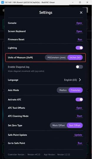
The Inch/mm mode can be changed using the button on the Settings page, or through G-code commands. The G20 command activates Inch mode, while the G21 command activates mm mode.
Mounting the Workpiece
Mounting the workpiece is detailed in the ‘8.4’ section. You can find detailed information on that section.
Workpiece Zero Setting
When working in 4th AXIS mode, the machine zeroing procedures according to the workpiece are explained below.
- Clamp the workpiece to the chuck and ensure there is no wobble.
- Set the speed to 5200 RPM, then click the Start button.
- As in Lathe mode, move down (X- direction) to a position away from the face of the workpiece, with the cutting tool tip aligned with the workpiece along the X axis.
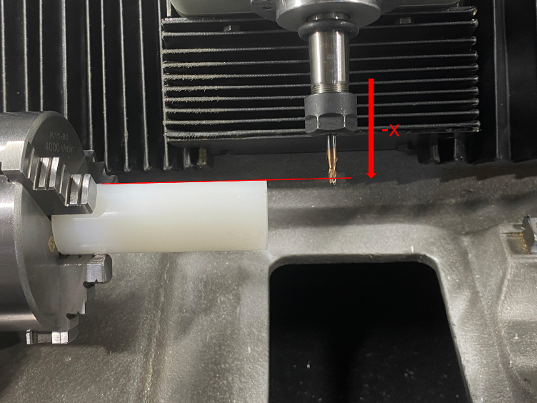
- Along the Z axis, approach until you hear a slight sound indicating contact between the cutting tool and the part.Note: When the cutting tool is closer than 5 mm to the workpiece, it is recommended to set the step size to 0.03 mm.
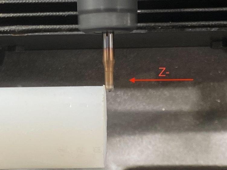
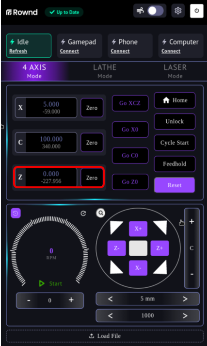
- At this first point of contact with the workpiece, press the “Zero Z” button to zero the Z axis.
- Move “+Z” direction and then move upward in the “+X” direction until you pass beyond the outer diameter of the part.
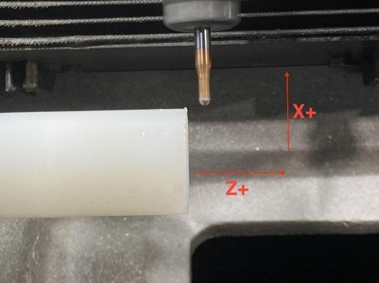
- Click the “Go Z0” button and observe that the cutting tool moves to align with the workpiece.
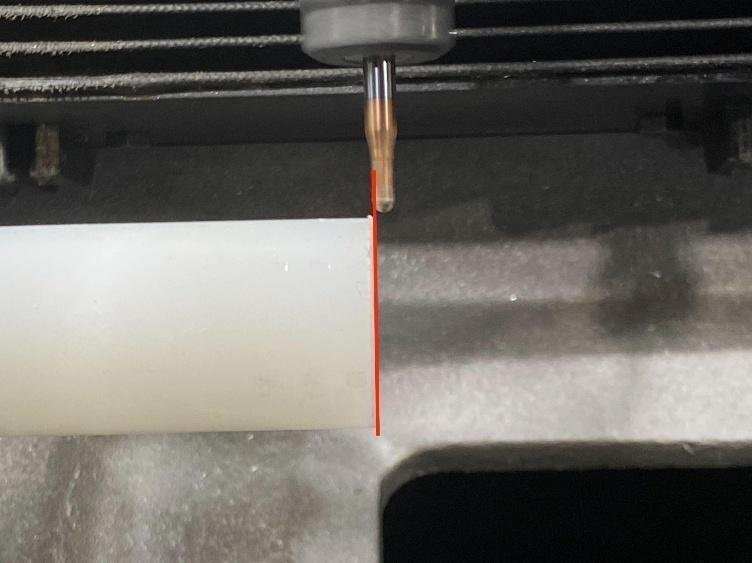
- Press the “Stop” button to stop the spindle rotation.
- If you do not know the exact diameter of the cutting tool you are using, measure it with a caliper.
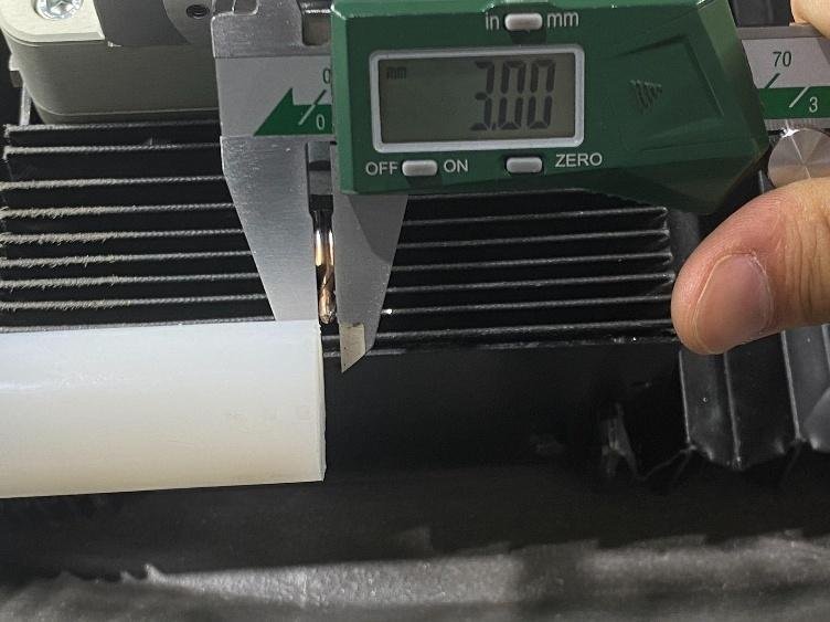
- Calculate half of the measured value.
- Set the speed to 5200 RPM, then click the Start button.
- Move in the -Z direction by the amount equal to half the thickness of the cutting tool calculated in item 10.
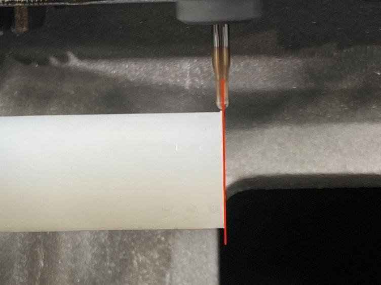
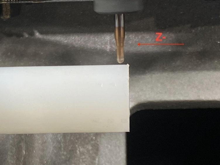
- Set the step size to 3 mm and the feed rate to 1000 mm/min, then click the “-Z” button once.
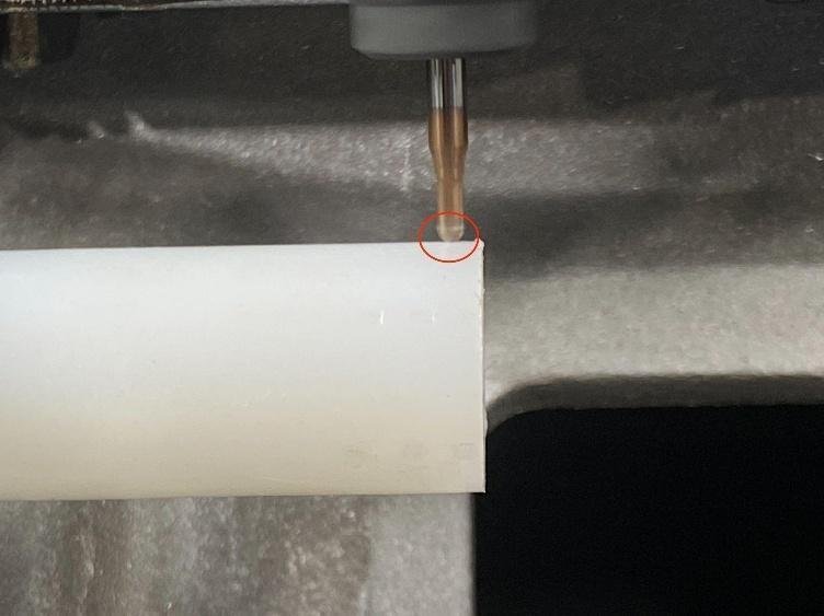
- Reduce the step size. When closer than 5 mm to the workpiece, set step size to 0.03 mm. Press the “-X” button to gently touch the workpiece. Continue until you hear a slight chip or sound.
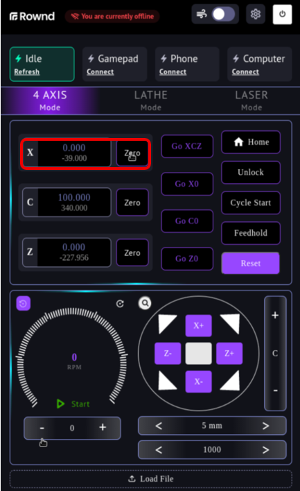
- Press the “Zero X” button to set this point as zero.
- Move 10 mm in the +X direction and 30 mm in the +Z direction away from the workpiece.
- Click the “Go X0” button and observe that your cutting tool aligns with the top surface of the workpiece.
- Press the “Stop” button to stop the spindle rotation.
- Measure and record the diameter of the workpiece.
- Calculate half of the measured value. This value represents the distance in millimeters between the tip of your cutting tool and the center of the workpiece.
- On the X-axis, move in the -X direction by the amount calculated in item 20.
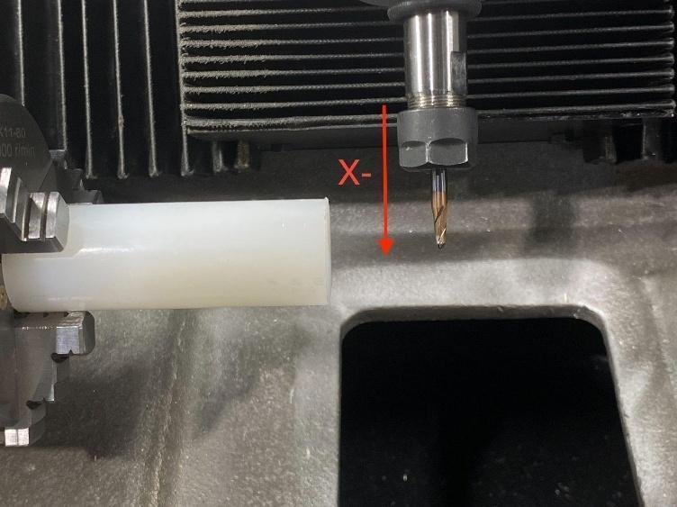
- Set this position to zero by pressing the “Zero X” button.
- Press the “Zero C” button to zero the C axis.
Running the G-Code File
You can follow the steps below to run your G-Code in 4AXIS mode. These steps are very similar to those explained in lathe mode.
1. Click the Load File button on the screen.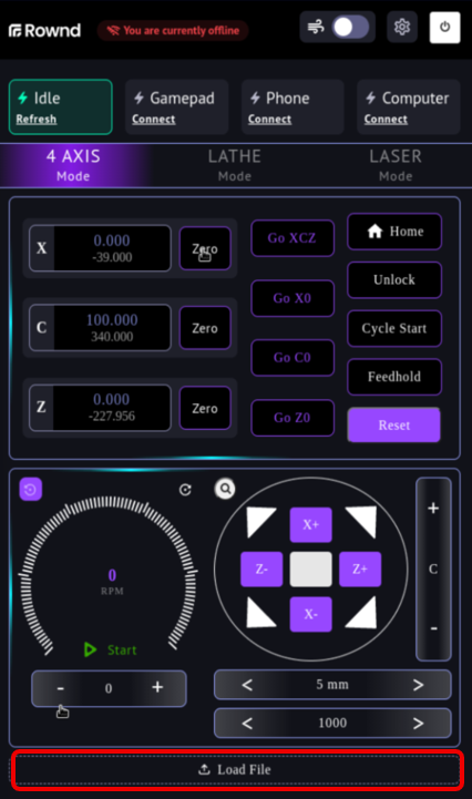
2. From the pop-up window, select Desktop and open the Demo Part folder.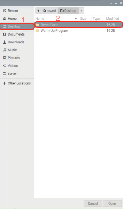
3. Open the 4th-Axis folder.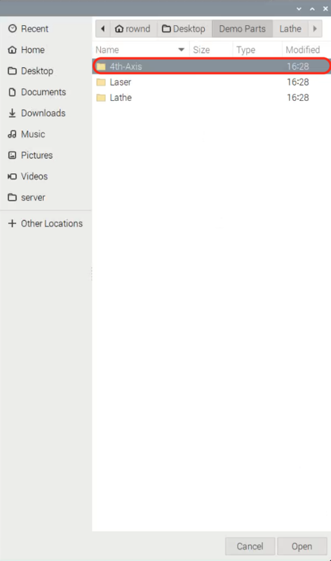
- Select the ‘4th-Axis_Demo.NC’ file and click ‘Open’.
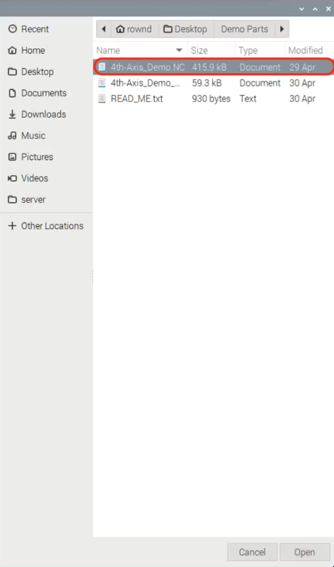
- You can either click the “Run” button to execute your G-Code directly or click the “Preview” button to review it before running.Note: While the machine is processing the part, closely monitor the machining and stay near the emergency stop button.
After the machine completes its operations, you are now ready to remove the processed material.
- 1.First, open the protective cover and remove the part from the chuck.
- 2.Clean your processed material using a brush.
- 3.Do not use any liquid substances to clean the material.
- 4.Clean out any chips that may have accumulated between the bellows.
- 5.Sweep all visible chips inside the machine into the chip bin.
9. Automatic Tool Changer (ATC)
Automatic Tool Changer (ATC)
Your machine's ATC mode, with its four-tool capacity ATC unit, provides the advantage of high precision and stable measurement during machining.
ATC Installation and First Experience
- Place the 4 M6 bolts into the attachment slot and tighten them using a 5 mm Allen key, following a cross-pattern sequence. Not: Ensure that the mounting surfaces are clean and free of chips.
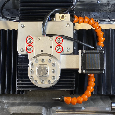
- Ensure all bolts are tight (Torque for M6 bolts: 10.5 Nm).
- Ensure there are no nicks or damage on the tool holder slots on the turret.
- Ensure there is no visible damage to the ATC motor cables.
- Ensure there are no worn (frayed) or broken parts.
- Ensure the ATC connector is seated correctly and firmly in its socket.
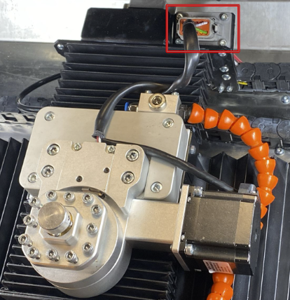
- Ensure your machine is in Lathe mode.
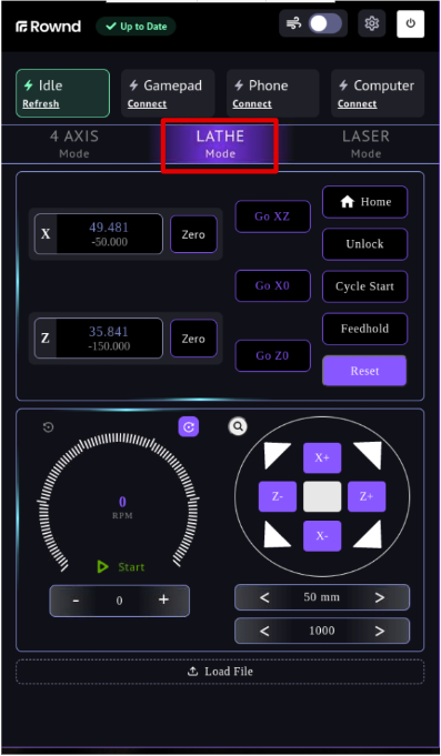
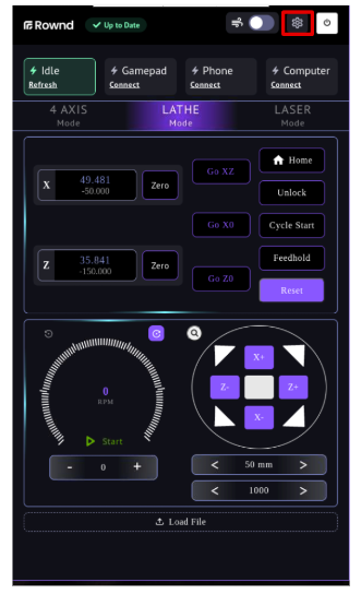
- Ensure your machine is in "idle" status.
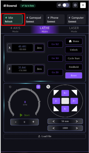
- Click on the "settings" menu button located in the top right corner of the screen.
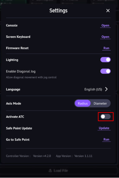
- Click on the "Activate ATC" button in the menu that opens.
- Carefully read the warning that appears on the screen and, if there are no obstacles to movement, click "Proceed." After this confirmation, the machine will first move upwards along the X+ axis until it reaches the end of the axis, and then move along the Z+ direction until it reaches the end of the axis.


- Do not send any commands to the system via the touch screen or external source (PC, USB, etc.) until the homing process is complete. When the process is finished, the ATC will be in the following position.
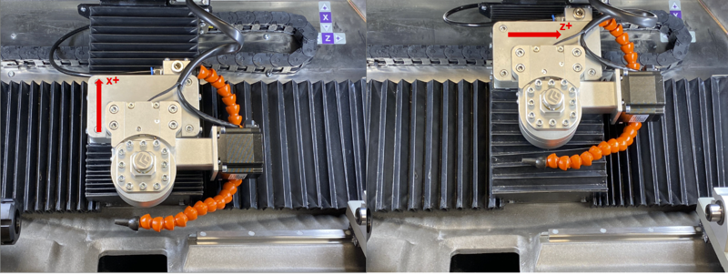
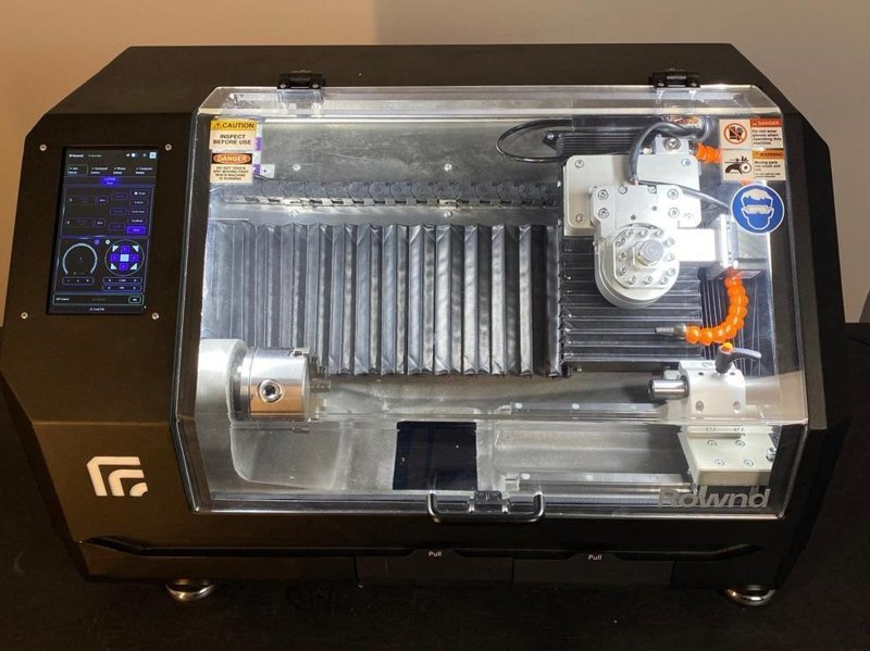
This position appears to be the same as the machine's home position, but it is actually the position defined as the safe point (G28). This position has a structure that can be changed and redefined according to operational needs.
When the ATC (Automatic Tool Changer) system is active on our lathe, it is mandatory to go to the G28 safe position before each tool change to prevent the turret from colliding with peripheral elements during rotation.
 |
 |
|---|
- Press the "Init" button and wait for the ATC to carry out the initialization process; during this time, do not send any commands to the system via the touch screen or external source (PC, USB, etc.).
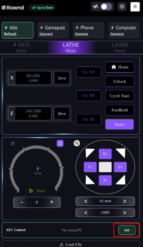 |
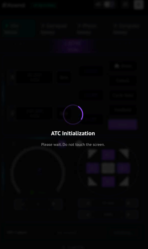 |
|---|
- After this process, the ATC determines the position of tool 1, thus preventing possible tool mix-ups.
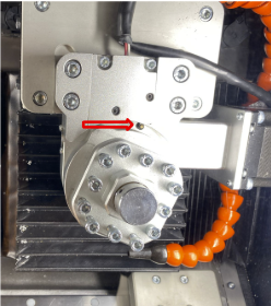 |
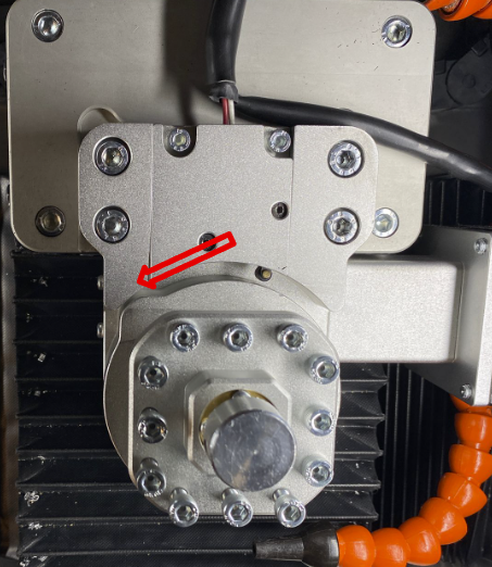 |
|---|
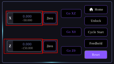
- Move 150mm in the -Z direction using the axis buttons, then move 50mm in the -X direction.
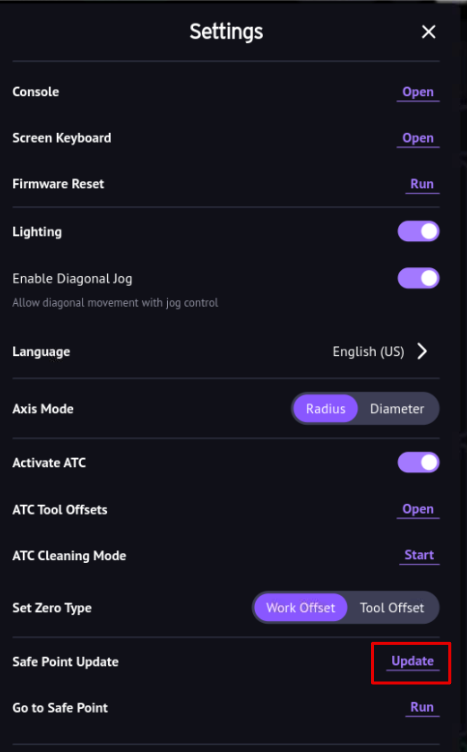
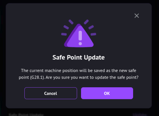
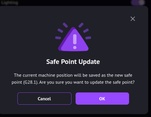
- Accept the current coordinate as the safe zone with the "Safe Point Update" button under the settings tab.
|
 |
|---|
- Zero the "X" and "Z" axes using the "Zero" buttons, and observe that "0.000" is displayed in the coordinate values.
- Adjust the distance to 10mm and the feed rate to 1000 mm/min using the axis buttons, then move once in the +z direction, then once in the +x direction.
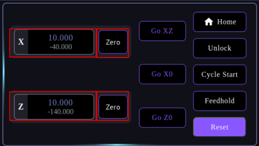
- At this point, accept the X and Z axes as zero again with the "Zero" buttons, click the "Go to Safe Point" button in the settings tab, and observe that the machine returns to its safe position on both axes.
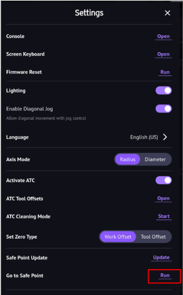
- On the ATC, mount the tool holder to slot number 1 on the turret. For this process, loosen the M5 bolts with a 4 mm Allen key, place the tool holder in the slot, and tighten the bolts onto the tool holder. Note: Avoid overtightening the bolts (maximum tightening torque for M5 bolts is 6 Nm).

- Click the "Select T2" button on the screen. When the ATC movement is complete, observe that the second tool is selected and the button changes to read "Selected T2"
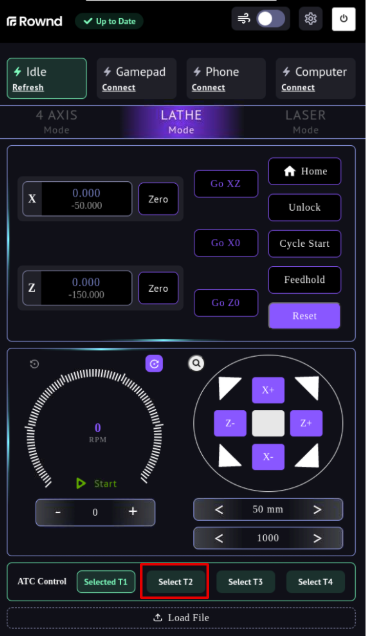

- Loosen the M5 bolts in slot number 2 of the ATC turret with a 4 mm Allen key. After fully seating the tool holder in the slot, complete the assembly by tightening the bolts. Note: Avoid overtightening the bolts (maximum tightening torque for M5 bolts is 6 Nm).Note: The ATC can be used with tool holders featuring a 10x10 mm shank or a Ø10 mm round shank. It is designed so that the insert sits 0.3 mm below the center of the spindle. Ensure proper centering using the shims provided with the ATC. For further details, please refer to item 12 under the QCTP Calibration section.


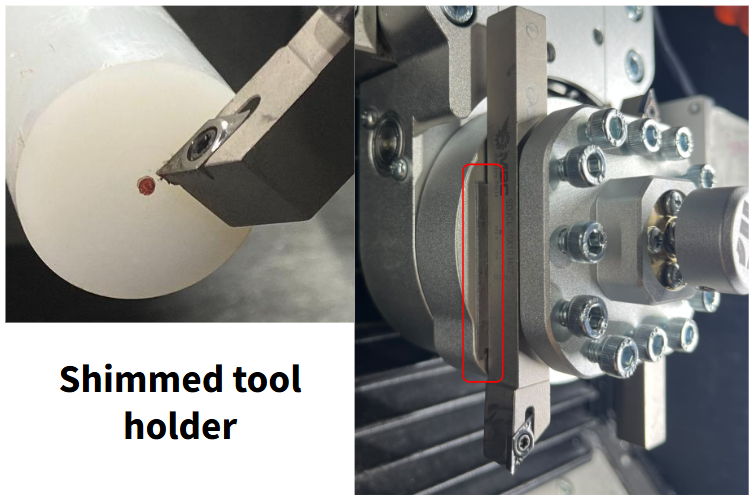
- Move 30mm in the -Z direction and 30mm in the +X direction using the axis control buttons.
- To return to tool 1, click the "select T1" button and observe that the ATC first reaches the safe zone (G28) and then rotates clockwise to catch tool 1.
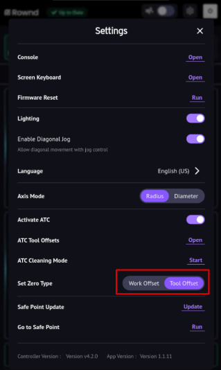
- Attach a plastic part onto the chuck.Note: During the tool 1 zeroing process, check the "Set Zero Type" expression under the settings icon and ensure "Work Offset" is selected.
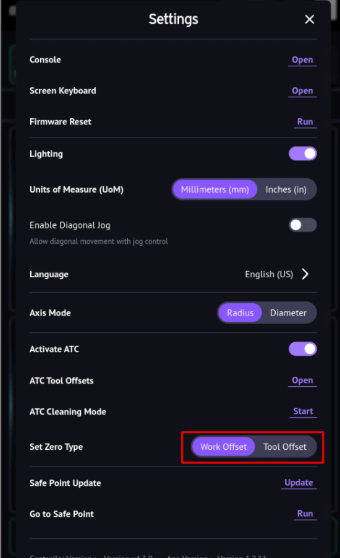
- As described under the "Workpiece Zero Setting" heading in the Rownd User Manual, take a small amount of chip from the face of the part and zero the last "Z" position where you took the chip using the "Zero" button next to the Z coordinate value.
- As described under the "Workpiece Zero Setting" heading in the Rownd User Manual, take a small amount of chip from the diameter of the part and zero the last "X" position where you took the chip using the "Zero" button next to the X coordinate value. Note: This process is not intended for defining the part zero; it is only a preparatory stage before entering tool offsets.
- Click the "Go XZ" button and observe that the cutting tool is at the height of the outer diameter of the part and aligned with the face area.
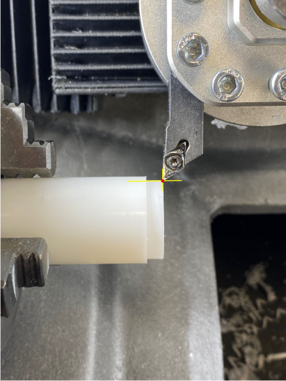
- Move a minimum of 20mm in the +X direction using the axis movement buttons.
- To select the second tool, click the "select T2" button, observe that the machine first goes to the G28 coordinate and then switches to tool 2.
- Give the chuck 2000 RPM speed and use the axis buttons to approach the diameter and face of the part where you took the chip. Your cutting tool should be 2mm inside the face area and at the last X distance where you took the chip.Note: The tool used in the description is for example purposes. You can also perform this process using any external diameter turning tool you wish.
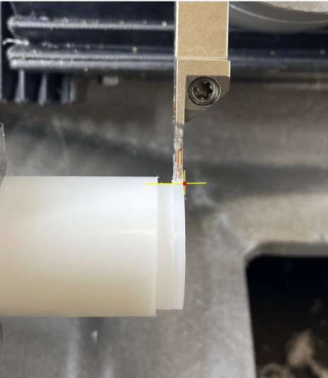
- Under the settings icon, change the "Set Zero Type" option to "Tool Offset".
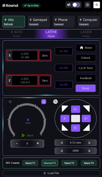
- Zero your tool on the part with the zeroing buttons on the screen.
- Click the "ATC Tool Offset" button under the settings icon and read the offset values of your tools on the screen that opens.
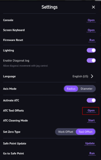
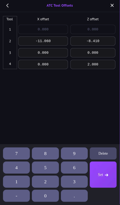
You can change the tool offset values via the numeric keypad that opens on this screen.
- Move a minimum of 20mm in the +X direction using the axis movement buttons.
- To select the first tool, click the "select T1" button, observe that the machine first goes to the G28 coordinate and then switches to tool 1.
- When you switch to the first tool, your coordinate values will change.
- Paint the face of the part attached to the chuck, where you took the chip, using a marker.
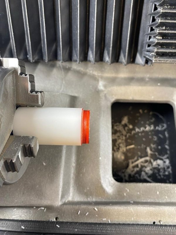
- Give the chuck 2000 RPM speed. Click the "Go XZ" button and observe that the machine goes to the position where you zeroed tool 1, and takes very little or no chips from the part.
- Click the "Stop" button to stop the chuck and move a minimum of 20mm in the +X direction using the axis movement buttons.
- To select the second tool, click the "select T2" button, observe that the machine first goes to the G28 coordinate and then switches to tool 2. After the tool change, the coordinate values you read on the screen will change.
- Give the chuck 2000 RPM speed and click the "Go XZ" button. Observe that the machine goes to the position where you zeroed the 2nd tool with the tool offset. As a result of this process, the machine will be at the "0.00" coordinate on the X and Z axes.
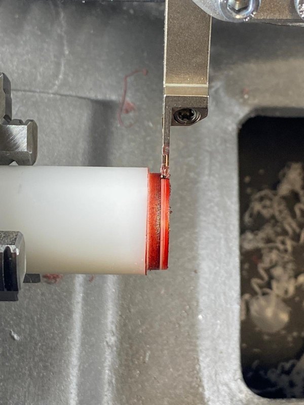
- Click the "Stop" button to stop the chuck and move a minimum of 20mm in the +X direction using the axis movement buttons.
- To select the first tool, click the "select T1" button, observe that the machine first goes to the G28 coordinate and then switches to tool 1.Note: In this system, the first tool had a specific zero point, and we zeroed the second tool at the same diameter but 2mm inside from the Z distance for control purposes.Note: Assuming that the second tool has been zeroed on the face of the part in this process. When you select the first tool and zero the center of the part, the second tool will also automatically be accepted as zero at the same point.Warning: When working with both a tool holder and a circular tool holder on the ATC, attention should be paid to the size relationship between the distance between the tools and the radius and length of the workpiece. When working with the tool holder, the machining to be done on the part must be smaller than the distance between the two tools. When working with the circular tool holder, the radius of the part must be smaller than the distance between the 2 tools.
Cleaning Mode
During or after machining a part with the ATC, chips may remain around the turret. To remove these chips more easily, click the "ATC Cleaning Mode" button under the settings icon.
 Note: When this button is clicked, the ATC will go to the G28 safe zone and the Turret will rise to its maximum height. In this way, you can easily clean the turret area of burrs.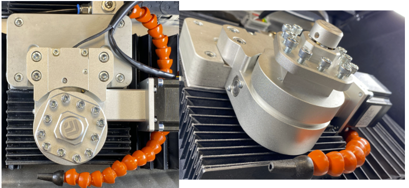
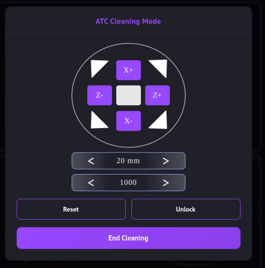
You can give axis movements at different step amounts and feed rates via the window that opens.
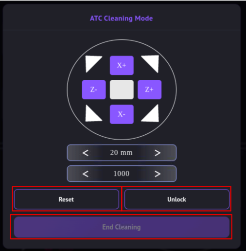
You can stop an unwanted movement with the "Reset" button. When the Reset button is active, the Machine does not receive any axis movement and the "End Cleaning" text becomes inactive. You must press the unlock key to finish the cleaning process or to give axis movement again.
ATC Maintenance
Daily Maintenance
After each use, the ATC must be put into "Cleaning Mode" and chips must be removed from it. You can use a brush, compressed air, or a vacuum during this cleaning.
Periodic Maintenance
The oil used inside the ATC must be replaced once a year. Even if the machine is not used, this maintenance must still be carried out annually
1- PH1 Phillips-head screwdriver
2- Oil seal removal tool
3- Grease (LGMT 2/1 SKF grease or similar types can be used)
4- Loctite 242 (blue)

- Remove the M3x8 DIN7985 screws
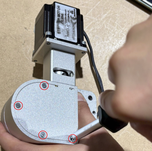
- Remove the bottom cover by gently prying it with a seal removal tool.
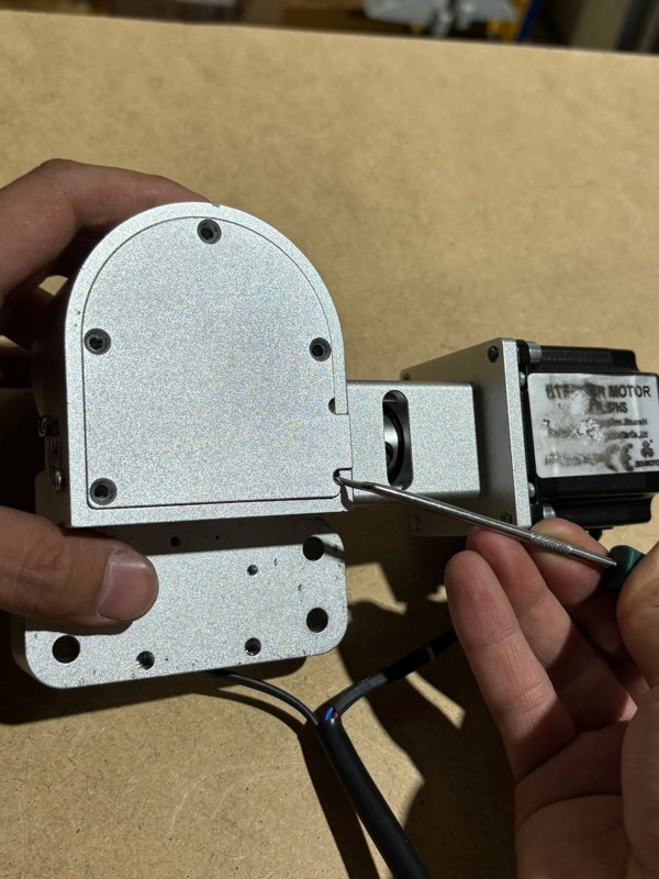
- Wipe away as much of the contaminated oil as possible using a cloth.
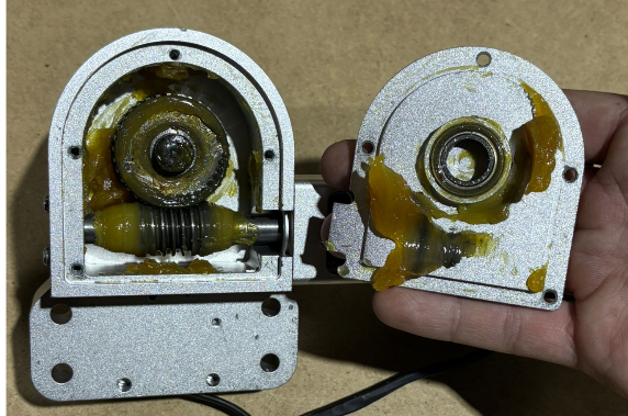
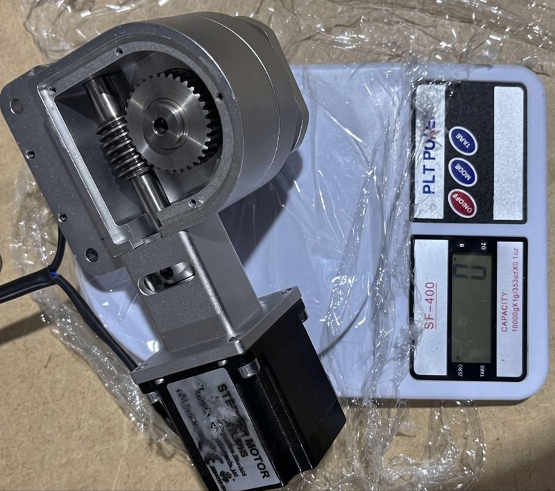
- Apply approximately 10 grams of oil between the gears and ensure it is distributed evenly.
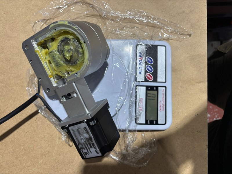
- Seat the rear cover into the bearing housing and ensure that the cover is fully seated against the body.
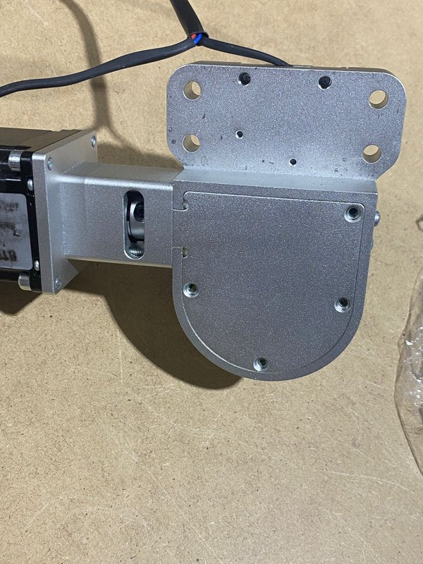
- Apply Loctite to the M3x8 DIN7985 screws.
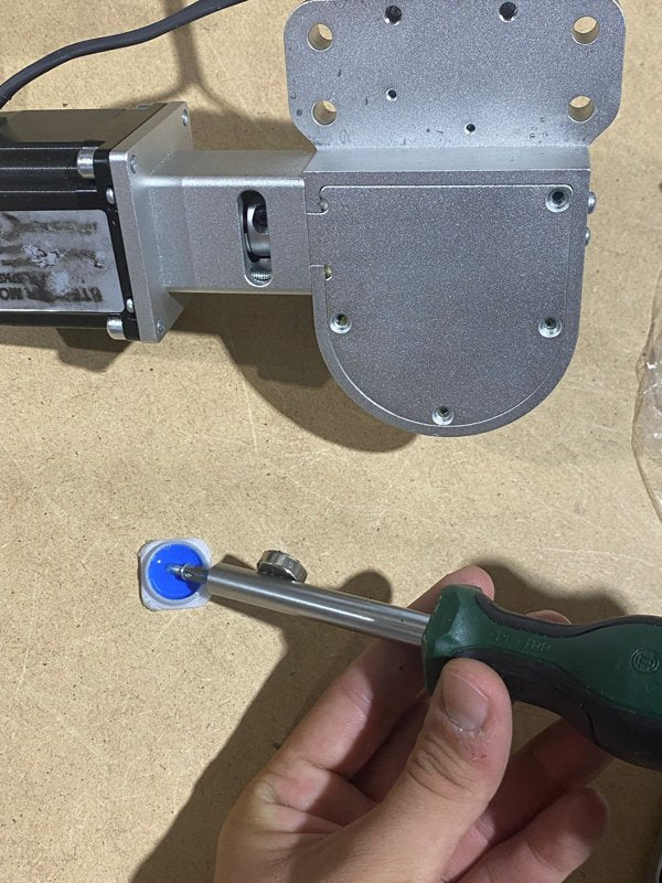
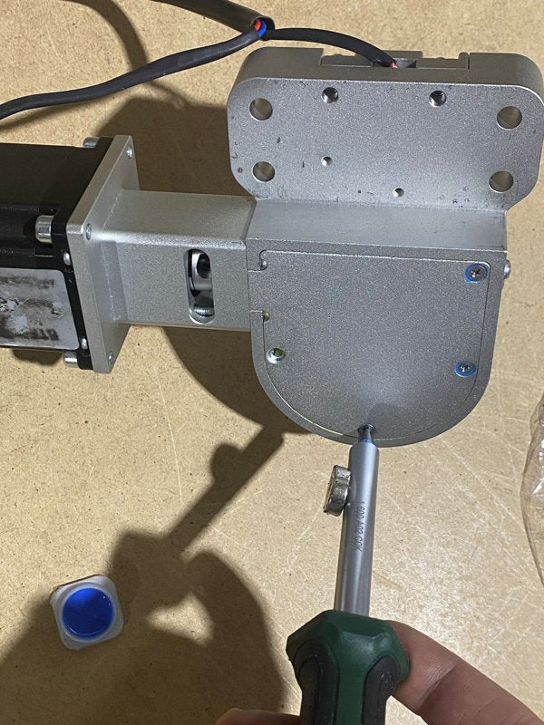
- securely tighten the rear cover to the body by hand.
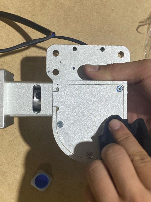
- Wipe away any Loctite and oil residues using a cloth.
ATC Troubleshooting
ATC Stuck on Switch
In this case, your machine will enter an alarm state. After switching to the idle state using the reset and unlock buttons, you can perform axial movements on the machine and continue operation.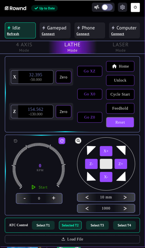
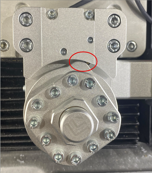
However, since a switch has been triggered, the machine will not perform homing under any circumstances and will be unable to carry out tool changes. 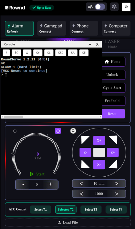
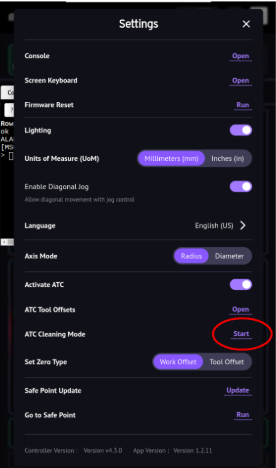
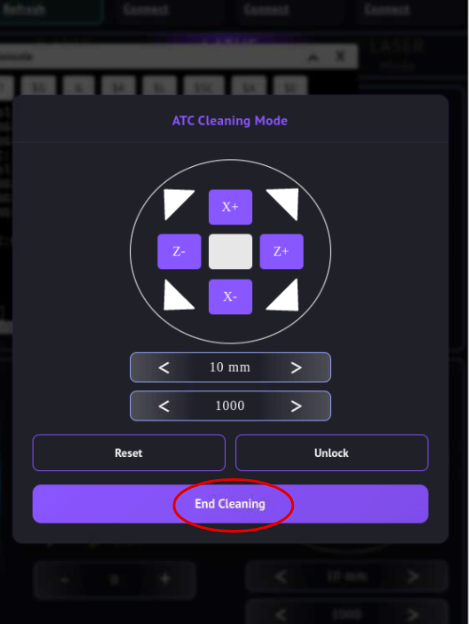
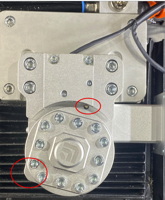
After clicking the "And Cleaning" button, observe that the ATC completes its initialization process and engages tool number one ("T1").
ATC Cleaning Mode Is Not Activate
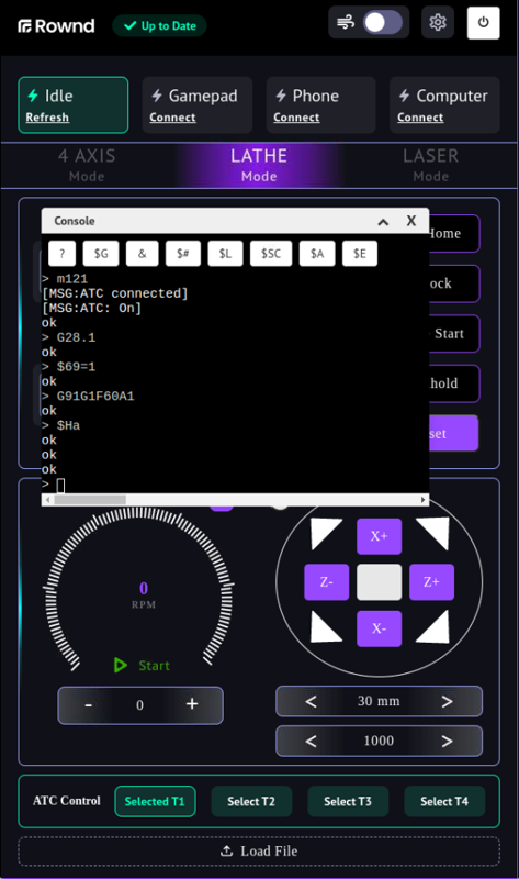
- Open the console from the settings tab
- Enter the following commands into the console line by line, and make sure you receive an "OK" feedback on every line.
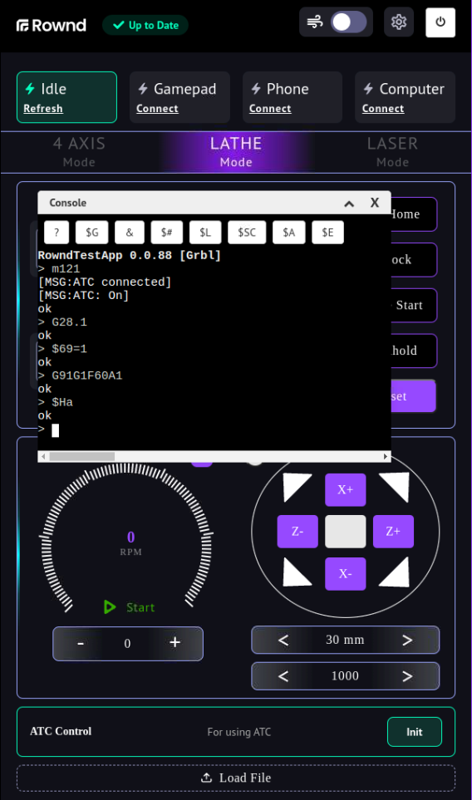
m121
G28.1
$69=1
G91G1f60a1
$Ha
Following these operations, the ATC position should be as shown below and ready for initialization. Press the 'init' button and observe that the ATC selected tool number one. 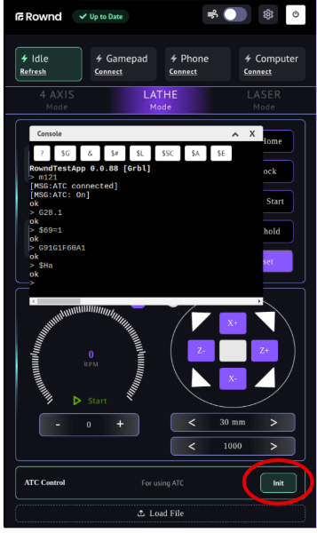
Tool Jamming During Tool Changes
Make sure to follow the steps above to verify that the ATC closes in the proper position.
If your ATC is having trouble completing tool changes, it’s usually because the ATC cap isn't set to the right height. This can happen over time from normal vibrations, shaking, or if the machine takes an impact.
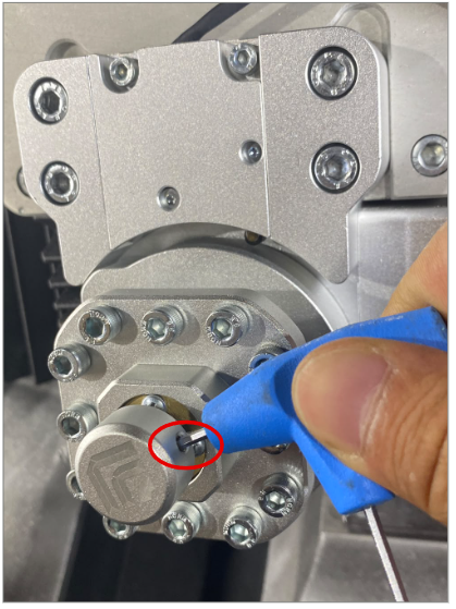
- Using a 2 mm Allen key, loosen the M4 set screws on both sides of the cap.
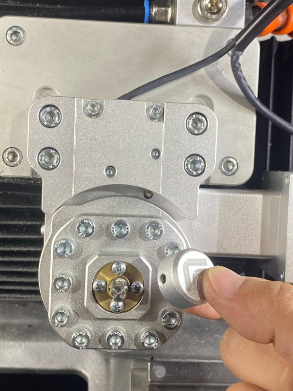
- Remove the ATC cap by pulling it upwards.
- Open the console from the settings tab
- Enter the following commands into the console line by line, and make sure you receive an "OK" feedback on every line.
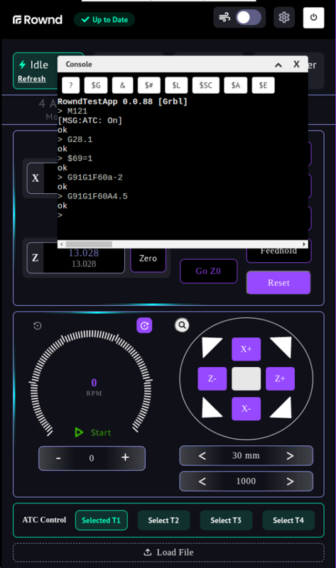
m121
G28.1
$69=1
G91G1f60a-2
G91G1f60a4.5
- Place the ATC cap onto the leadscrew, ensuring the set screws align with the flat surfaces, and verify that the cap makes full contact with the screws on the turret.
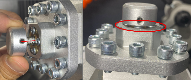
- Retighten the M4 set screws.
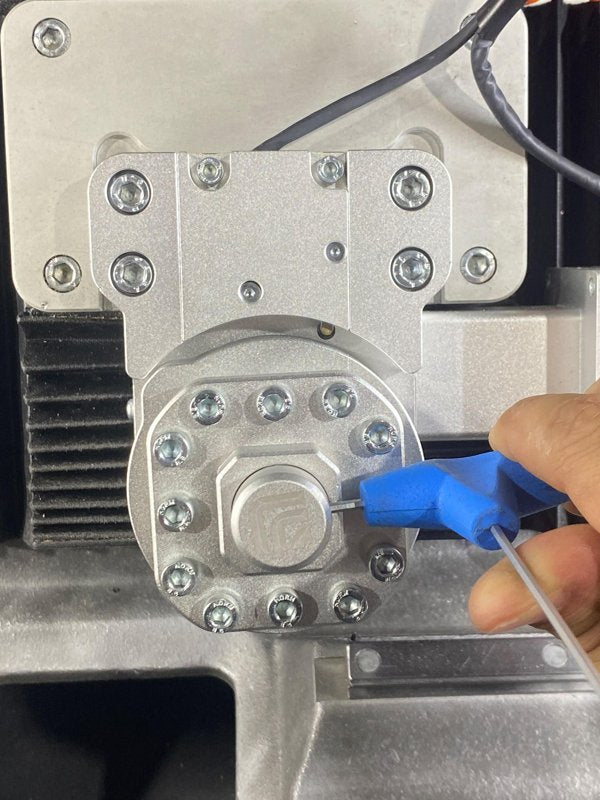
- Open the console from the settings tab
- Enter the following commands into the console line by line, and make sure you receive an "OK" feedback on every line.
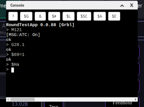
m121
G28.1
$69=1
$Ha
- Upon completing this process, the machine will perform the ATC initialization and select tool 1.
10. Laser Module Operations
Laser Mode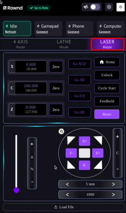
The Laser Mode of your machine is used for laser operations when the Laser Add-on is attached. The model included in your product list is Laser D-B10W, which uses a 10W laser. This mode is not suitable for cutting; it is designed for engraving on the surface of wood and some plastics.Warning: Some plastics may release toxic gases when processed. Therefore, proper ventilation and safety precautions must be ensured during laser operation
Pre-check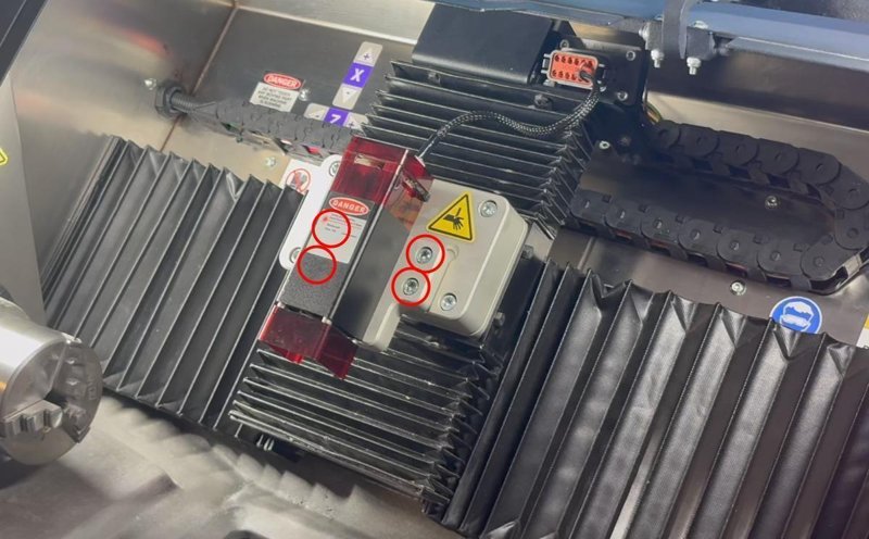
- Using a 5 Allen key, insert the 4 screws into the add-on slot and tighten them gradually in a criss-cross pattern.
- Ensure all screws are tight.
- Ensure that the slides are in good condition without any nicks or damage.
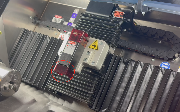
- Ensure that there are no frayed or broken parts.
- Make sure the protective glass is properly mounted on the laser device.
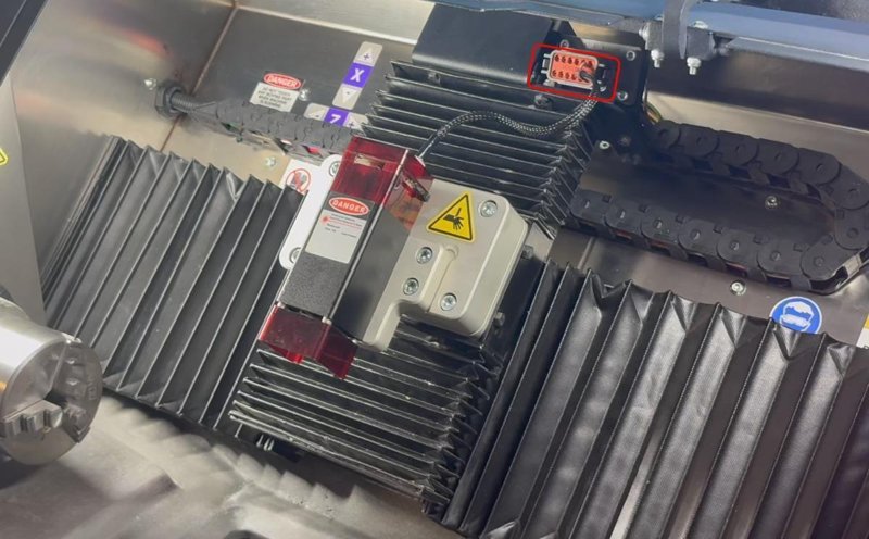
- Make sure the laser connector is properly connected to the add-on connector.
- Ensure that the Warm-up program is applied after opening the machine.
- Ensure that you wear the laser safety goggles.
| Check the machine's state; if it is in alarm mode, click the “reset” and then “unlock” buttons sequentially and ensure it changes to “idle” mode. |  |
|---|---|
| Press the “Laser” button on the screen to switch to laser mode. | 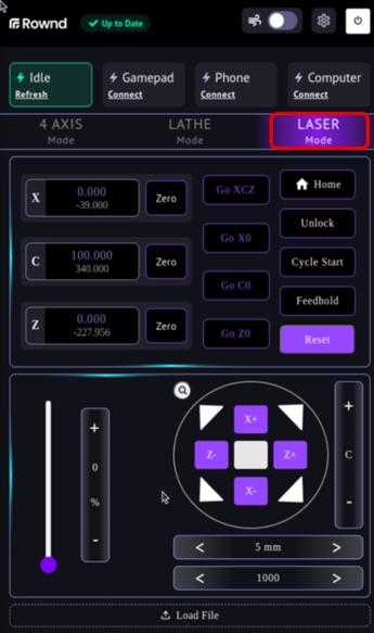 |
In addition to the control buttons explained in Lathe and 4AXIS modes, follow the steps below to learn the function of the laser power bar.
- Click the “Home” button to make the machine move to its home (zero) positions.
- Click the “z-” button to move 150mm to the left along the Z axis.
- Click the “x-” button to move 50mm down along the X axis.
- At this position, click the “zero X,” “zero Z,” and “zero C” buttons to zero all three axes.
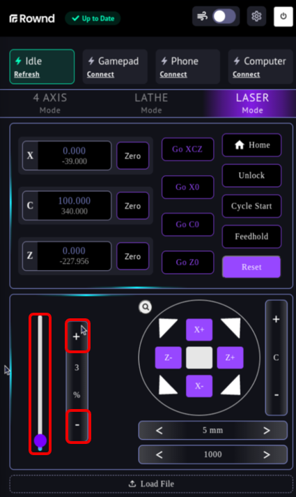
- To power the laser, use the power bar on the left side of the screen and click the “+” button once to set the power to 3%.Note: To emit the laser beam, you must first move the axis. The laser will not emit while the machine is idle.
- Set the step size to 10 mm and the feed rate to 200 mm/min, then click the “+Z” button. Observe that the laser starts working as soon as the axis movement begins.
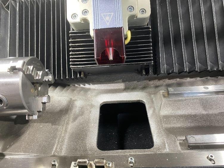
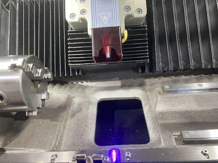
- Set the step size to 20 mm and the feed rate to 200 mm/min. Move in the “-X” direction, and before the movement completes, click the “FeedHold” button. Observe that the laser stops emitting as the axis motion halts.

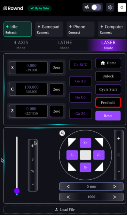
- Click the “Cycle Start” button and observe that the laser starts emitting again as the axis begins to move. The machine remains in the “Run” state until the movement is completed.
- To turn off the laser, either drag the power bar to zero or use the “+” and “-” buttons to reduce the power to zero.
- Set laser power to 3%.
- Set step size to 10 mm and feed rate to 100 mm/min. Click “X-” to move in -X direction. Before movement finishes, open the protection cover. Machine stops. State changes to “Door”.

.
- Close the protection cover. Click the “Reset” button, then the “Unlock” button. Observe that the machine is now in “Idle” state.
- Set the power as %3, Set step size to 10 mm and feed rate to 100 mm/min. Click “X-” to move in -X direction. Before movement finishes, open the protection cover. Ensure that Machine stops and state changes to “Door”.
- Close the protection cover, click the “Cycle Start” button, and observe that the axis movements continue.
Laser Interface
Mounting the Workpiece
Mounting the workpiece is detailed in the ‘8.4.’ section. You can find detailed information on that section.
Laser Setting the Zero
Ensure that Laser mode is selected before setting the zero.
- Position your laser using the axis buttons so that it stays in the top-right position relative to the workpiece.
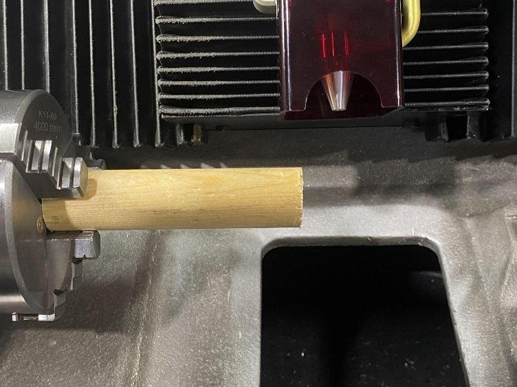
- Set the laser power to 3%.
- To zero your workpiece on the Z-axis, slowly approach the part in the “-z” direction.
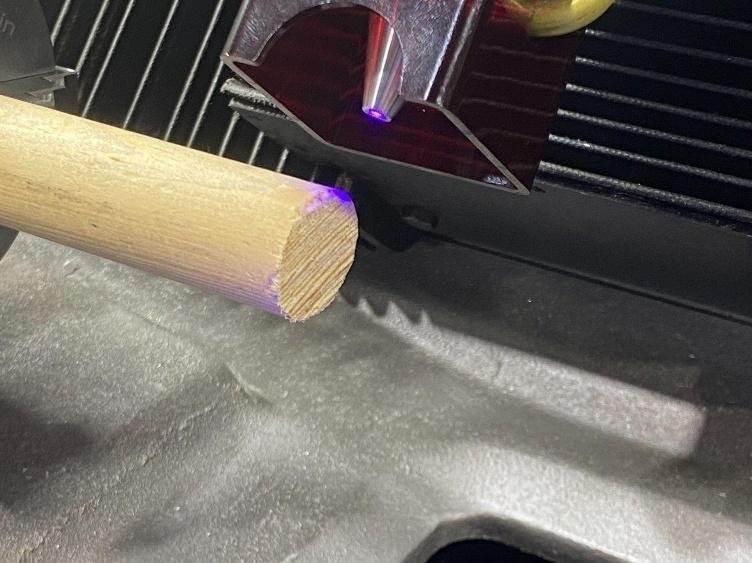
- When the laser beam first reaches the surface of the workpiece, click the “Zero Z” button and set the part zero on the Z-axis.
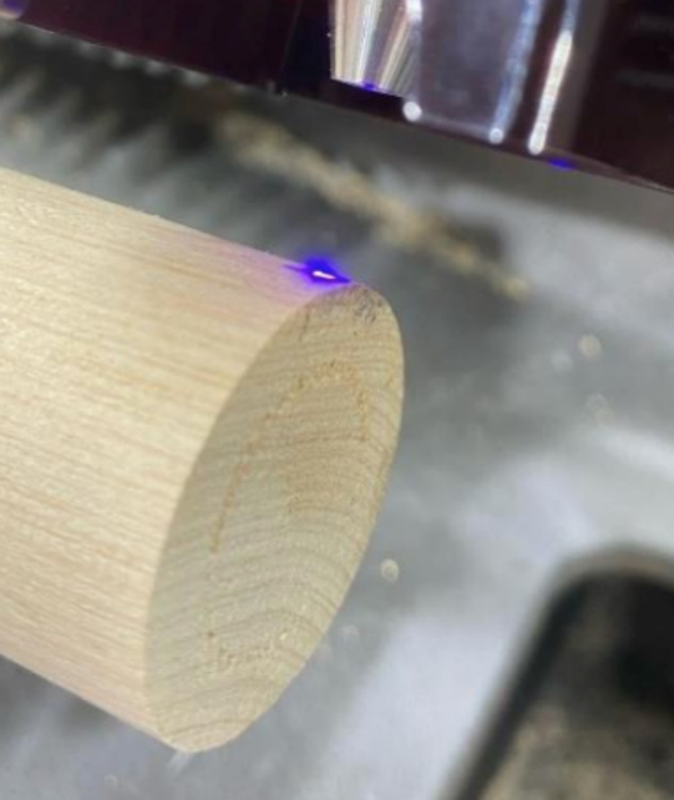
- Set the laser power to “0” and make sure the laser is turned off.
- Slowly move the laser protection cover down along the X-axis in the “-x” direction until it touches the workpiece.
| When the laser’s protective glass touches the workpiece, move the laser 7mm in the +X direction and set this position as zero by pressing the “Zero X” button. | 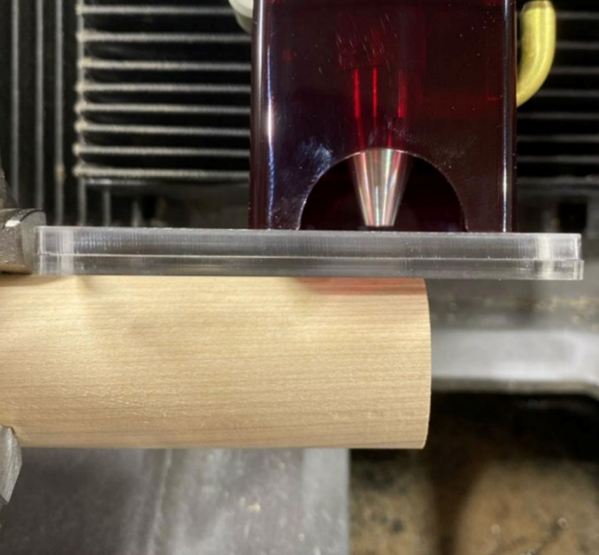 |
|---|
Running the G-Code File
You can follow the steps below to run your G-Code in LASER mode. These steps are very similar to those explained in lathe or 4 AXIS mode.
- Click the Load File button on the screen.


2. From the pop-up window, select Desktop and open the Demo Part folder.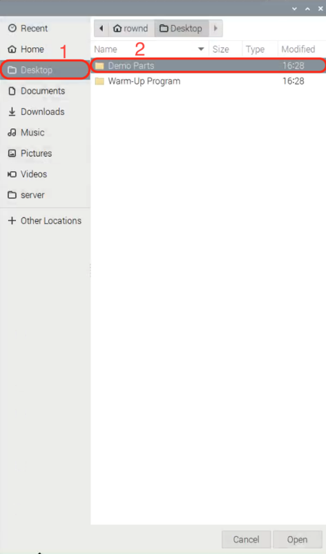
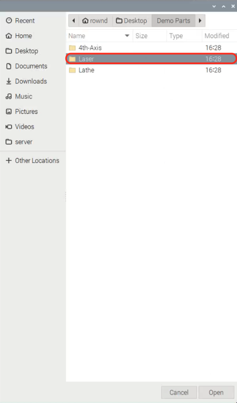
3. Open the Laser folder.
4.Select the ‘Laser_Demo.NC’ file and click ‘Open’.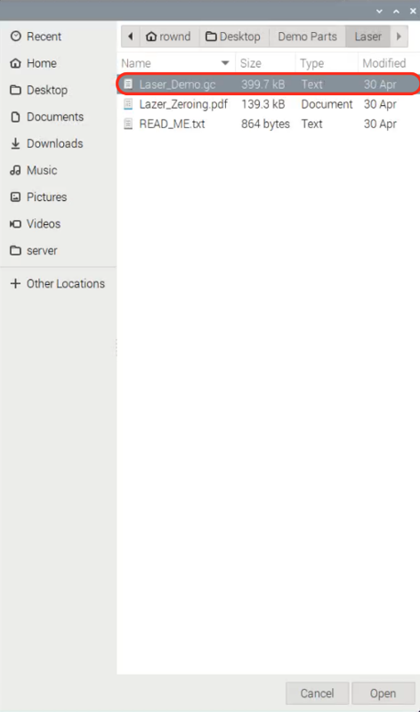
5. You can either click the “Run” button to execute your G-Code directly or click the “Preview” button to review it before running.
.
After the machine completes its operations, you are now ready to remove the processed material.
1. First, open the protective cover and remove the part from the chuck.
2. Do not use any liquid substances to clean the material.
11. Connectivity & Controls
Connection Methods
Rownd CNC Lathe offers 3 different connection options with various control interfaces. Through these methods, you can send motion commands to the machine, load G-codes, and monitor machine-related data.
Mobile Application
This mobile application, specially developed by Rownd Precision Industry, is designed for you to connect and control your machine. Through the app, you can manually operate the machine, send and run G-codes, and view daily, monthly, and yearly usage times. Additionally, you can use the Lathe, Laser, and 4th-Axis modes via the application.
- Download the Rownd Mobile App.
- To turn on your machine’s Bluetooth, connect a mouse to the machine.
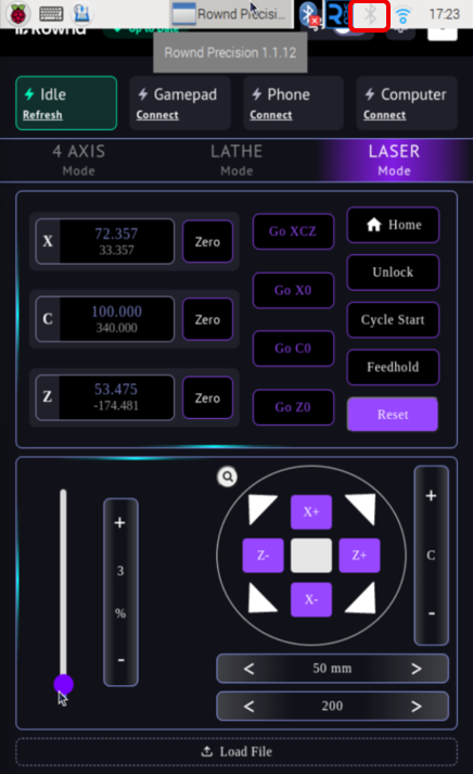

- Move the cursor toward the top edge of the screen. Click the Bluetooth icon and then click ‘Turn on Bluetooth.’ Your machine’s Bluetooth will now be visible through the mobile app.
- Launch the Rownd app on your phone.
- Click the "Connect to Rownd" button.

7. Select your machine on the screen and proceed.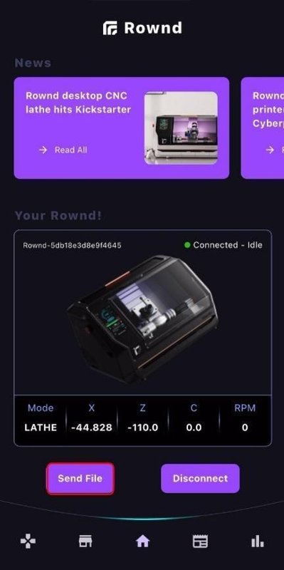
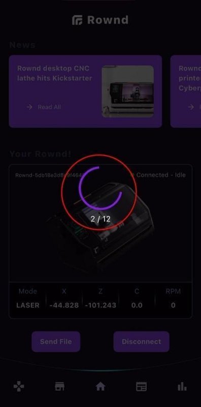
8. To upload a G-Code to the machine via the mobile app, tap the "Send File" button, select the G-Code file you want to upload, and wait for the file to transfer to the machine.
9. You can control the machine with same buttons with touchscreen and monitor the operations from the page where you manually control your machine.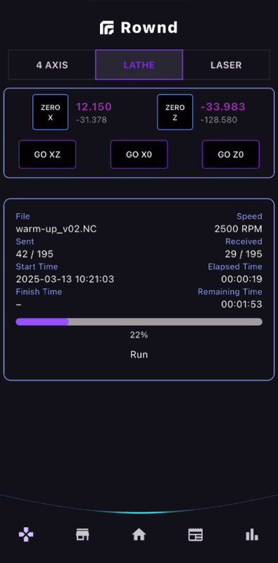
Computer Connection
Thanks to the mini-USB port on the machine body, you can easily connect the machine to your computer using the mini-USB cable provided. This connection can be made through any G-Code sender software. With the computer connection, you can manually control your machine or run G-Code. You can also switch between Lathe, Laser, and 4th-Axis modes and run G-Code in any of these modes.
How to Connect the Computer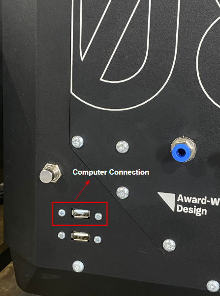
You can use any program with G-Code sender capabilities to control your machine and run G-Code from your computer.
| First, press the "KVM Switch" button located on the left side of the machine, above the USB ports, until you hear a click. This button disconnects the application on the machine and allows you to connect directly to the computer. Note: Make sure your machine is in the ‘Idle’ state. Note:When you press the button, observe that you receive the warning: "The serial port '/dev/ttyUSB0' is disconnected". |
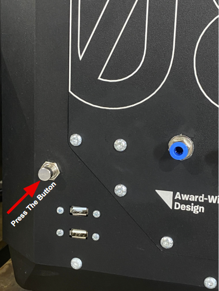 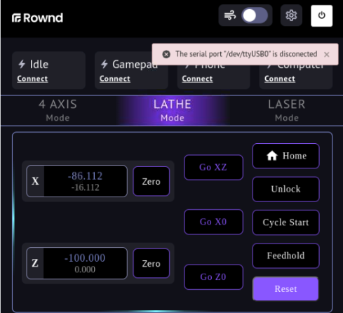 |
|---|---|
| Connect the USB cable that comes with your machine to the machine’s USB port as shown below, then open your G-code sender application on your computer. | 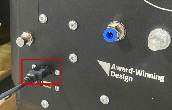 |
| Set the baud rate to 115200. | 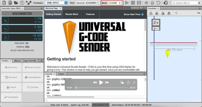 |
| Select the COM port. Note: You can find the COM port your machine is connected to in the Device Manager. |
 |
| In the firmware section of the UGS program, select GRBL. Note: In some software or different versions of UGS, you may need to select GRBL ESP32 instead of GRBL in the firmware section. |
 |
| Click the connect icon. |  |
How to Use the App
After deciding which mode your G-code will run on, type the command $37 in the console to see the current mode of your machine.
- If the response is AsdaCN1, the machine is in Lathe Mode.
- If the response is PWM, the machine is in 4th-Axis Mode.
- If the response is Laser, the machine is in Laser Mode.
To switch between modes, use the command:
- Lathe: AsdaCN1
- 4th-Axis: PWM
- Laser: Laser
Transferring and Running the G-Code File
- Click folder icon.
- Select the G-Code file you want to load in the dialog window and click the “Open” button.
- Click the ‘Start’ icon and confirm that the state shows ‘Run’.
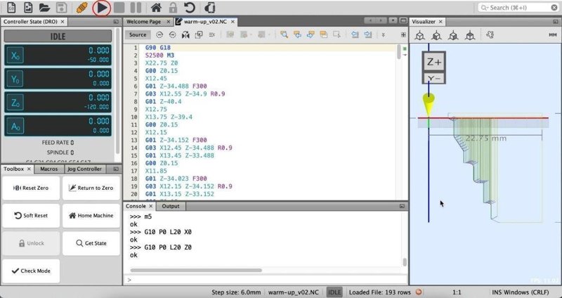
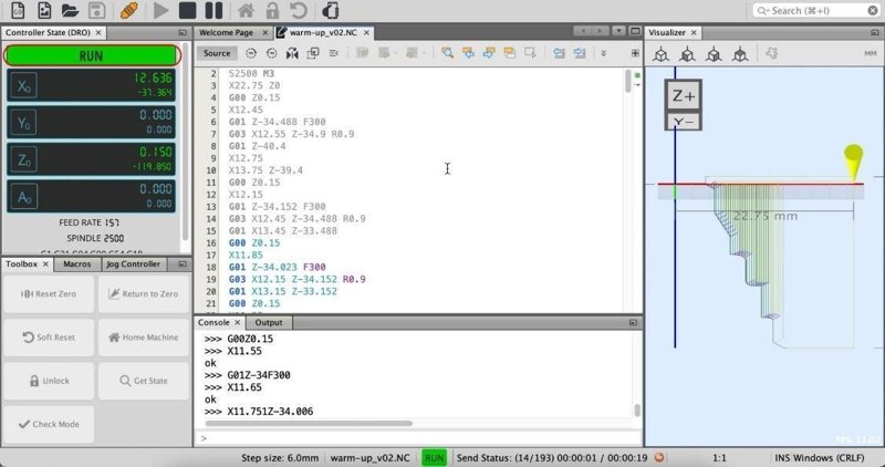
Gamepad
The gamepad connection allows you to manually control your machine remotely. It makes part zeroing operations easier.
Gamepad Controls
Square: Initiates the Homing Process
Cross: Sending Zero Point for X and Z Axes
Triangle: Starts the Chuck Rotation
Circle: Stops the Chuck Rotation
R2: Increases the Chuck RPM
L2: Decreases the Chuck RPM
R1: Increases Feed Rate
L1: Decreases Feed Rate
Right Analog: Manual Axis Control
Left Analog: Chuck Position Control in 4th-Axis Mode
Touchpad: Cursor Control on touchscreen
How to Connect Gamepad
You can connect the gamepad to your machine either via USB or Bluetooth.
To connect with a USB Cable, follow these steps;
- Plug the gamepad into the machine using a USB cable.

- Power on the gamepad.
- The device will be automatically recognized, and you can start using it immediately.

To connect with a Bluetooth, follow these steps:
- Make sure that the machine’s Bluetooth is turned on.
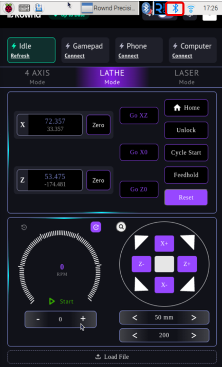
- Tap the Bluetooth icon on the screen and select your gamepad.
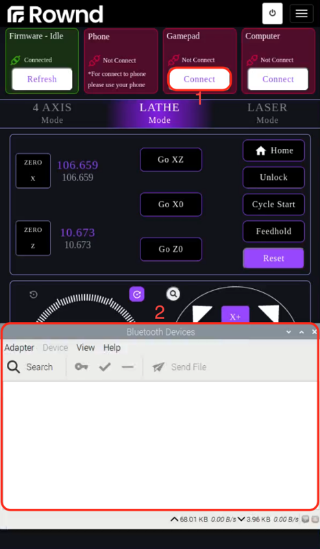
- Once paired, the gamepad will be ready for use.
Waste Disposal
Waste disposal laws and regulations differ across countries and regions. When disposing of waste, be sure to be aware of the local laws, regulations, and guidelines regarding waste disposal.Note: You can contribute to recycling by collecting the different parts produced by your machine in separate containers.
12. Maintenance & Power-off Guide
Before turning off the power to your machine, first shut down the machine’s operating system.
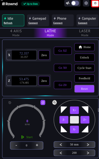
- Click the power button located at the top right corner of the screen, as shown in the image below.
- In the pop-up window that appears, click the “Yes” button and follow the screen to ensure the machine shuts down completely.
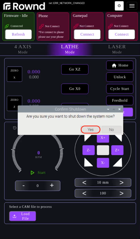
- Turn off the power switch located on the power socket on the side of the machine and unplug the power cable.
This section explains the daily, periodic, and spindle maintenance of the machine. You can access the videos explaining each of these via the QR codes provided.Note: To ensure the stable operation of your machine, it is recommended to connect a Wi-Fi and perform regular updates.
Daily Maintenance
These are the maintenance tasks that should be performed at the end of each day the machine is used. Generally, they involve cleaning and lubrication of the machine.
1- Sweep the coarse chips inside the machine into the chip box using a brush.
2- Clean the chips remaining in narrow areas using compressed air or a vacuum.
3- Empty the chips collected in the chip drawer.
4- Clean the chips that have gone to the bottom of the machine using a vacuum.
- Lubricate the chuck surface and jaws using a brush.
- Lubricate the tailstock linear slides.
- Lubricate the tailstock slides through the lubrication holes.
- Lubricate the QCTP tool holder.
- Lubricate the chuck through the oil hole.
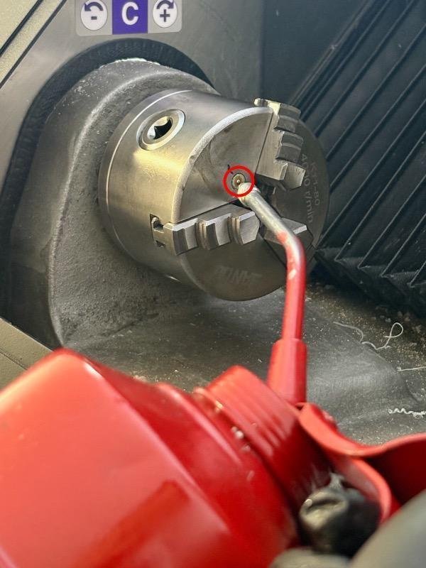
Periodic Maintenance
The machine's periodic maintenance is performed monthly with an average daily usage of four hours.
The tools you will need for maintenance are: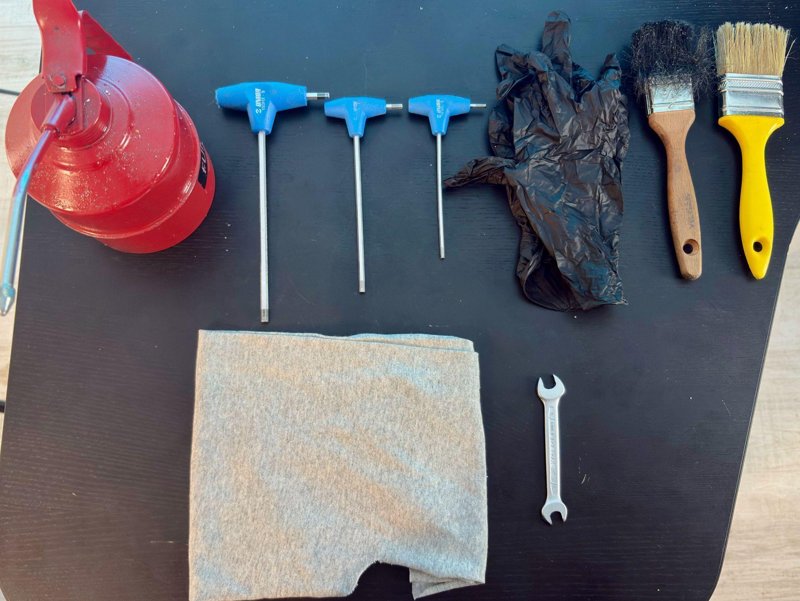
- Metric 8 wrench.
- Metric 3,4,5 allen wrench.
- Sliding surface oil of ISO VG68
- Brush
- Cleaning cloth
- Vacuum
- Gloves
- Move the axis 150 mm in the Z-direction and 50 mm in the X-direction from the home position.
- Turn off the machine's power.
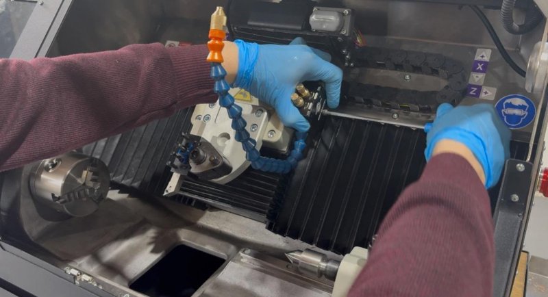
- If the machine has an air-cooling option, first remove the hose and then the air-cooling unit using a size 4 allen wrench.
- Remove the add-on top mounting part using a size 4 allen wrench.
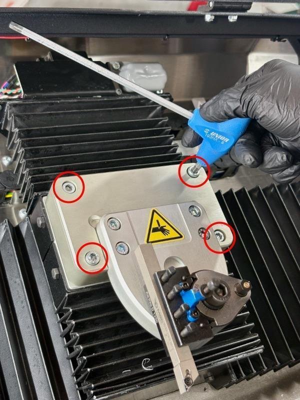
- Remove the 6 bolts securing the X-axis bellows to the connection part using a metric 8 wrench.
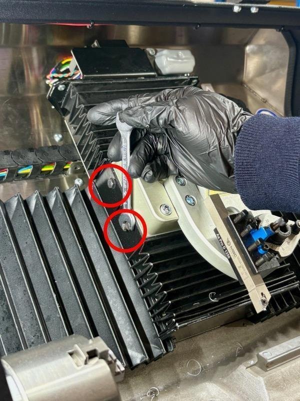
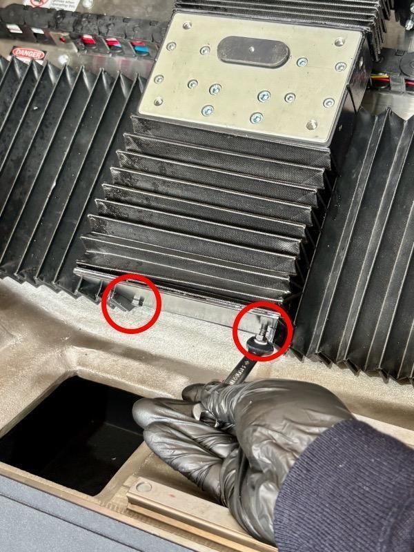
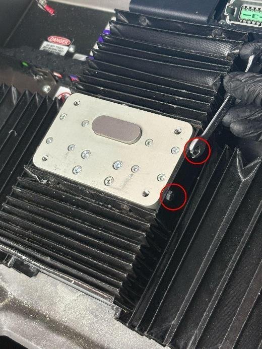
- Move the X-axis bellows as shown in the following photos.Hint: Stretch one side and pull it sideways and upwards. Also, remove the bottom X-axis bellows.
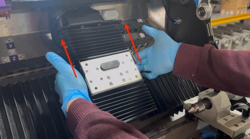
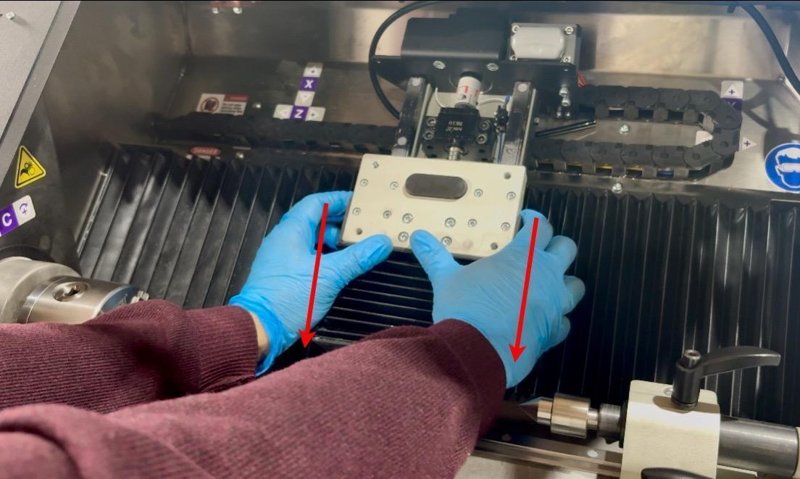
- Remove the 8 bolts securing the Z-axis bellows to the connection part using a metric 8 wrench.

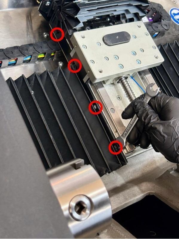
- Open one side of the Z-axis bellows. Hint: Stretch one side and pull it sideways and upwards.
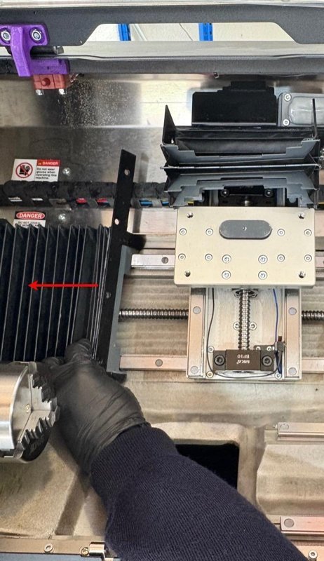

- Clean the area under the bellows using a vacuum cleaner, brush, or cloth. Warning: Make sure that no damage is caused to the switches during the cleaning process.


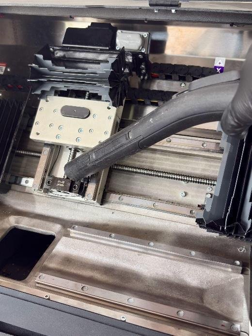
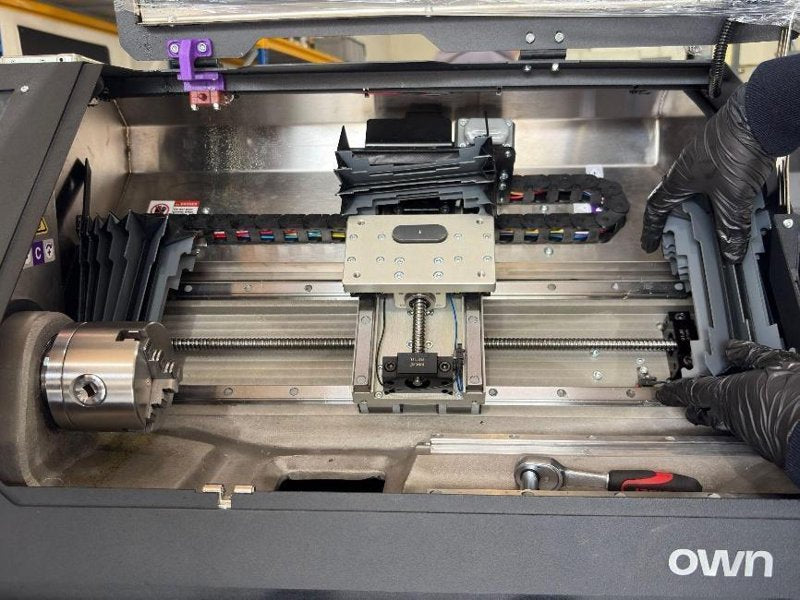
- Lubricate the linear slides, lead screw, lead nut, bearings, and slide carriages.
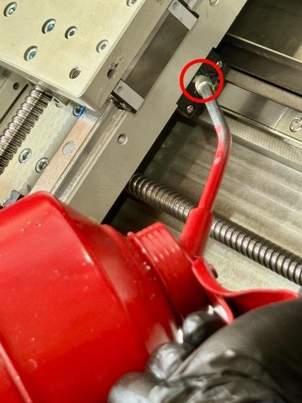
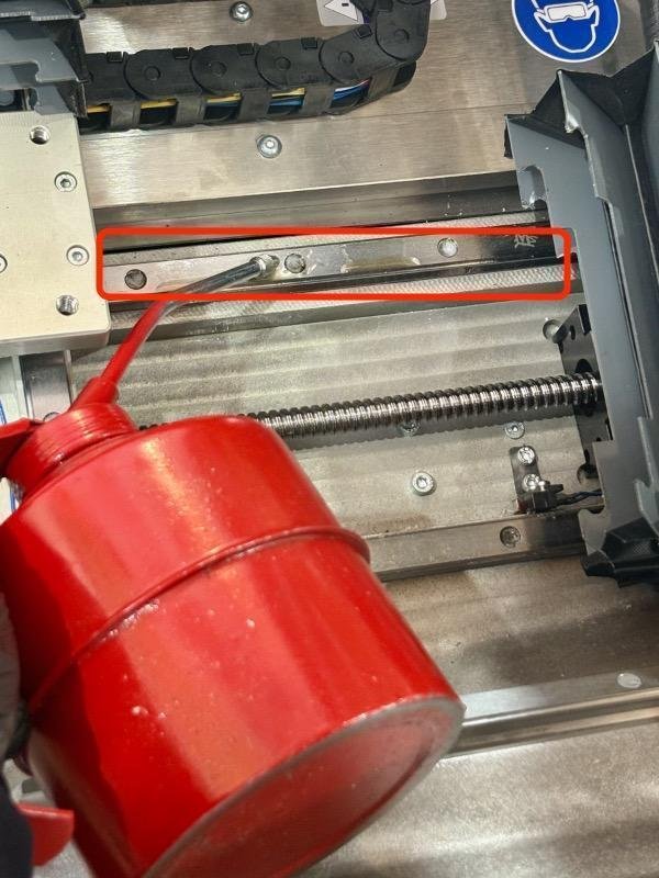
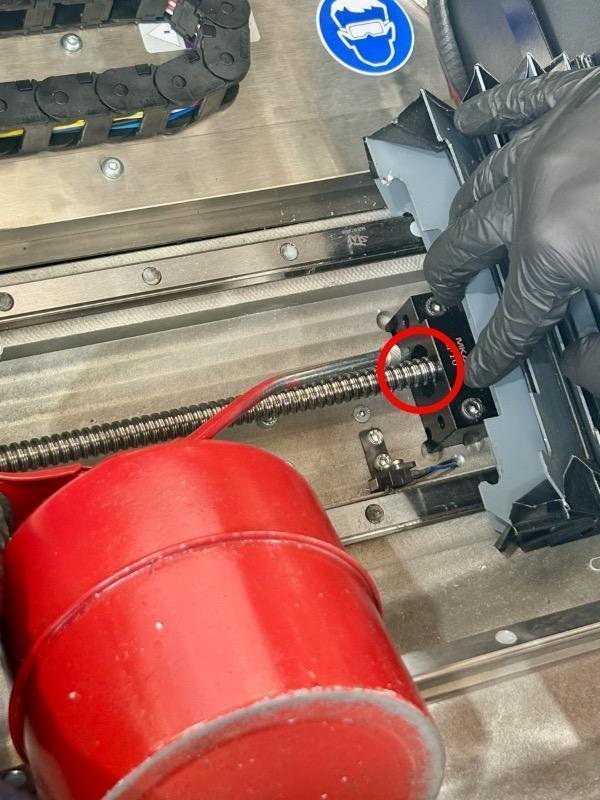
- Place the Z-axis bellows into the channels and tighten the 8 bolts.
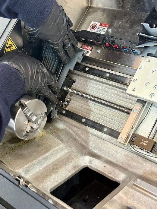
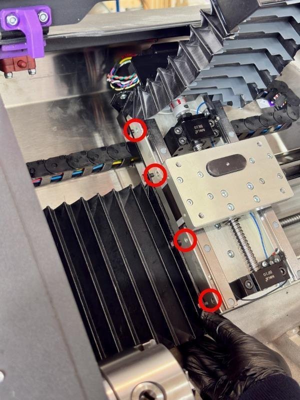
- Place the X-axis bellows into the channels and tighten the 6 bolts.
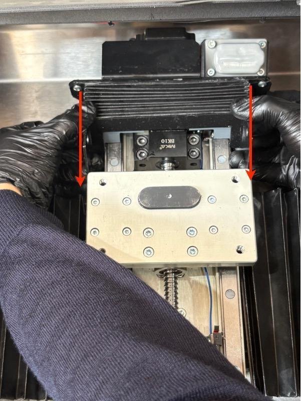
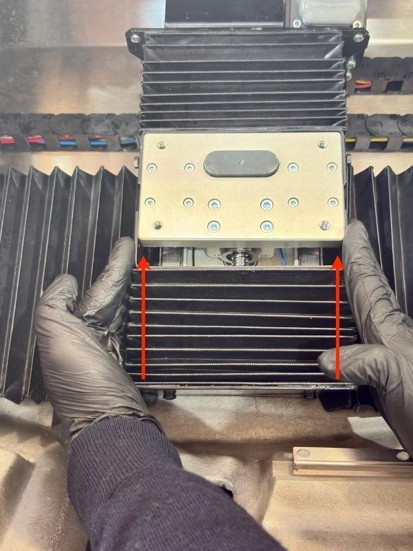
- Place the add-on top mounting part using a size 4 allen wrench.
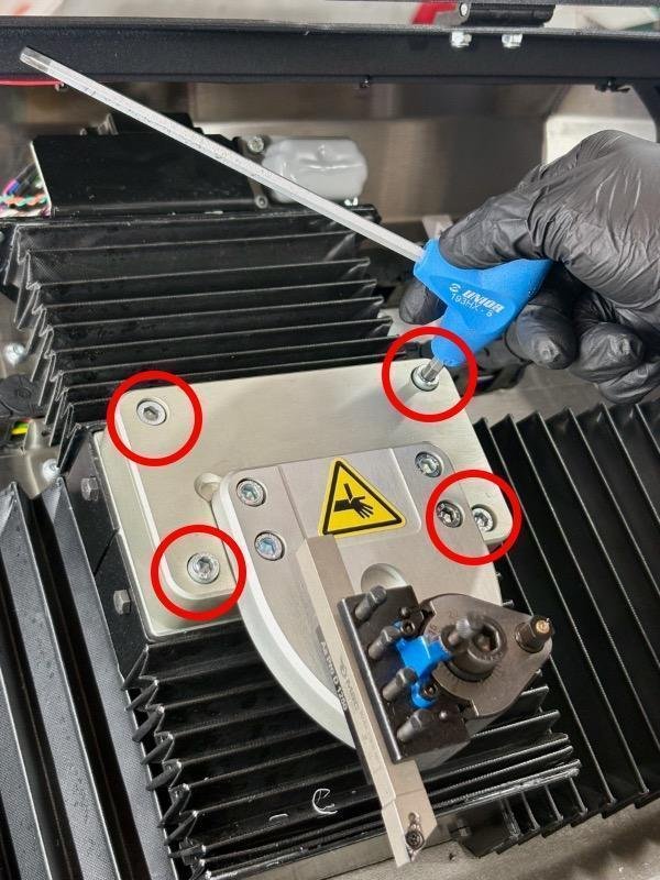
- Remove the 12 bolts of the left service cover.
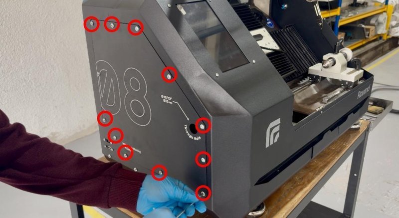
- Clean this area of the machine with a vacuum.
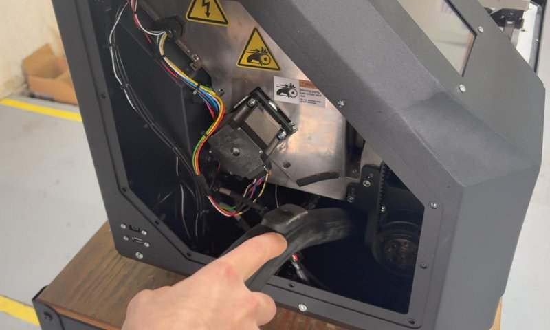
- Place the left service cover back and tighten the 12 bolts.
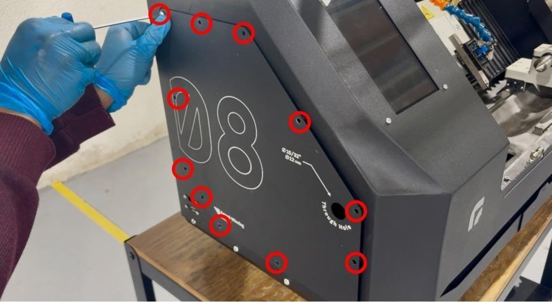
13. Troubleshooting Matrix
| No | Problem | Possible Cause | Solution |
|---|---|---|---|
| 1 | The machine is stuck on the “Loading” screen after selecting a file. | The USB flash drive is not inserted, or the file is missing from the drive. | Check if the USB is properly inserted and the file exists inside the USB flash drive. |
| 2 | Spindle does not rotate even though RPM is shown on screen. | Spindle add-on not receiving power, wiring is loose or software issue. Spindle driver is in Alarm. | Check DT connector connections and make sure cables are properly plugged in. Re-power the machine. |
| 3 | The laser module does not work. | Laser not enabled or no axis movement. | Ensure that the axis is moving while the laser module is operating. Also, check the 24V power line and the laser signal cable connections. |
| 4 | No display on screen after power up. | HDMI or power cable is disconnected. | Reconnect HDMI and USB cables; make sure LED on screen is lit. |
| 5 | Machine cannot complete the homing process. | One or more axis limit switches are triggered or malfunctioning. | Ensure that none of the machine's axes are physically pressing against the limit switches. If the problem persists, inspect the limit switches for mechanical or electrical faults. |
| 6 | Chuck jaws do not meet at the center when tightened. | Jaws may have been installed in the wrong numbered slots. The jaw replacement procedure may not have been followed correctly. |
Ensure that each chuck jaw is installed in the correct slot according to its number. Double-check that the jaw replacement process has been completed exactly as described in the user manual, without skipping any steps. |
| 7 | The machine does not power on, or power is lost during operation. | The 10A fuse located in the AC power switch may have blown. | Remove the blown fuse from the AC power switch and replace it with a new 10A fuse. If the machine still does not receive power, or if the new fuse blows again, please contact our technical support team for further assistance. To ensure stable operation and protect the system from voltage fluctuations, using a voltage regulator is highly recommended. |
14. Supported G/M Codes & Disclaimers
Supported G and M Code List
This section provides the G and M codes supported by your machine.
G Code List
-G00 Rapid Move
For rapid linear (straight line) motion, program G0 'axes', where all the axis words are optional. The G0 is optional if the current motion mode is G0. This will produce coordinated linear motion to the destination point at the maximum rapid rate (or slower). It is expected that cutting will not take place when a G0 command is executing.
-G01 Linear Move
For linear (straight line) motion at programmed feed rate, program G1 'axes', where all the axis words are optional. The G1 is optional if the current motion mode is G1. This will produce coordinated linear motion to the destination point at the current feed rate.
-G02, G03 Arc Move
A circular or helical arc is specified using either G2 (clockwise arc) or G3 (counterclockwise arc) at the current feed rate. The direction (clockwise, counterclockwise) is as viewed from the positive end of the axis about which the circular motion occurs.
-G04 Dwell
The P number is the time in seconds that all axes will remain unmoving. The P number is a floating-point number so fractions of a second may be used. G4 does not affect spindle, coolant and any I/O.
The usage format is: G4 P-.
-G10 L1 Set Tool Table
G10 L1 sets the tool table for the P tool number to the values of the words. A valid G10 L1 rewrites and reloads the tool table.
The usage format is: G10 L1 P- axes <R- I- J- Q->. P is tool number, R is radius of tool, I is front angle (lathe), J is back angle (lathe), Q is orientation (lathe).
-G10 L2 Set Coordinate System
G10 L2 offsets the origin of the axes in the coordinate system specified to the value of the axis word. The offset is from the machine origin established during homing. The offset value will replace any current offsets in effect for the coordinate system specified. Axis words not used will not be changed.
The usage format is: G10 L2 P-. P is coordinate system (0-9)
-G10 L20 Set Coordinate System
G10 L20 is similar to G10 L2 except that instead of setting the offset/entry to the given value, it is set to a calculated value that makes the current coordinates become the given value.
The usage format is: G10 L20 P- axes. P is the coordinate system (0-9).
-G20, G21 Units
G20 is to use inches for length units. G21 is to use millimeters for length units.
-G28, G28.1 Go to Predefined Position
G28 uses the values stored in parameters as the X Z C* final point to move to. The parameter values are absolute machine coordinates in the native machine units.
G28 makes a rapid move from the current position to the absolute position of the values in parameters. G28.1 stores the current absolute position into parameters. G28 axes make a rapid move to the position specified by axes including any offsets, then will make a rapid move to the absolute position of the values in parameters for axes specified. Any axis not specified will not move.
*C Axis only available in 4th-Axis and Laser Mode. In Lathe mode, it is not valid.
-G30, G30.1 Go to Predefined Position
G30 functions the same as G28 but uses the values stored in parameters as the X Z C* final point to move to. G30 makes a rapid move from the current position to the absolute position of the values in parameters. G30.1 - stores the current absolute position into parameters. G30 axes make a rapid move to the position specified by axes including any offsets, then will make a rapid move to the absolute position of the values in parameters for axes specified. Any axis not specified will not move.
*C Axis only available in 4th-Axis and Laser Mode. In Lathe mode, it is not valid.
-G38.x Straight Probe
G38.2 means probe toward the workpiece, stop on contact, signal error if failure. G38.3 means probe toward the workpiece, stop on contact. G38.4 means probe away from workpiece, stop on loss of contact, signal error if failure. G38.5 means probe away from workpiece, stop on loss of contact
-G43 Tool Length Offset
G43 enables tool length compensation. G43 changes subsequent motions by offsetting the axis coordinates by the length of the offset. G43 does not cause any motion. The next time a compensated axis is moved, that axis’s endpoint is the compensated location.
The usage format is G43 <H->. H is a tool number, and it is optional.
-G49 Cancel Tool Length Compensation
G49 cancels tool length compensation. It is OK to program using the same offset already in use. It is also OK to program using no tool length offset if none is currently being used.
-G53 Move in Machine Coordinates
To move in the machine coordinate system, program G53 on the same line as a linear move. G53 is not modal and must be programmed on each line. G0 or G1 does not have to be programmed on the same line if one is currently active.
The usage format is G53 axes.
-G54 to G59 Select Coordinate System
G54 means select coordinate system 1, G55 means select coordinate system 2, G56 means select coordinate system 3, G57 means select coordinate system 4, G58 means select coordinate system 5, G59 means select coordinate system 6.
-G76 Threading Cycle
The tool is moved to the initial X and Z positions prior to issuing the G76. The X position is the drive line, and the Z position is the start of the threads. The tool will pause briefly for synchronization before each threading pass, so a relief groove will be required at the entry unless the beginning of the thread is past the end of the material or an entry taper is used.
The usage format is: G76 P- Z- I- J- R- K- Q- H- E- L
P is the thread pitch in distance per revolution.
Z is the final position of threads. At the end of the cycle the tool will be at this Z position.
I is the thread peak offset from the drive line. Negative I values are external threads, and positive I values are internal threads.
J is a positive value specifying the initial cut depth. The first threading cut will be J beyond the thread peak position.
K is a positive value specifying the full thread depth. The final threading cut will be K beyond the thread peak position.
R is the depth degression.
Q is the compound slide angle is the angle (in degrees) describing to what extent successive passes should be offset along the drive line. This is used to cause one side of the tool to remove more material than the other.
H is the number of spring passes. Spring passes are additional passes at full thread depth.
E specifies the distance along the drive line used for the taper.
L specifies which ends of the thread get the taper.
-G90, G91 Distance Mode
G90 means absolute distance mode in absolute distance mode, axis numbers represent positions in terms of the currently active coordinate system.
G91 means incremental distance mode in incremental distance mode, axis numbers represent increments from the current coordinate.
-G92 Coordinate System Offset
G92 makes the current point have the coordinates you want without motion, where the axis words contain the axis numbers you want. All axis words are optional, except that at least one must be used. If an axis word is not used for a given axis, the coordinate on that axis of the current point is not changed. When G92 is executed, the origins of all coordinate systems move. They move such that the value of the current controlled point, in the currently active coordinate system, becomes the specified value. All coordinate system’s origins are offset by this same distance.
The usage format is G92 axes
-G92.1 Reset G92 Offsets
G92.1 resets G92 offsets to zero and sets parameters to zero.
-G93, G94 Feed Rate Mode
G93 is Inverse Time Mode. In inverse time feed rate mode, an F word means the move should be completed in, one divided by the F number, minutes.
G94 is Units per Minute Mode. In units per minute feed mode, an F word is interpreted to mean the controlled point should move at a certain number of inches per minute, millimeters per minute, or degrees per minute, depending upon what length units are being used, and which axis or axes are moving.
M Code List
The codes M100, M101, M102, M120, M121, M150, and M151 are custom M-codes developed by Rownd Precision Industry specifically for this machine. In addition to these, general-purpose M-codes are also supported. All supported M-codes are explained below.
-M0 Program Pause
M0 pauses a running program temporarily. Pressing the resume button will restart the program at the following line.
-M2, M30 Program End
M2 ends the program. Pressing ‘run’ will restart the program at the beginning of the file.
M30 same as the M2. It ends the program. Pressing ‘run’ will restart the program at the beginning of the file.
-M3, M4, M5 Spindle Control
M3 starts the selected spindle clockwise at the “S” speed. M4 starts the selected spindle counterclockwise at the “S” speed. M5 stops the selected spindle.
-M6 Tool Change
To change a tool in the ATC from the tool currently in the ATC to the tool most recently selected program M6. When the tool change is complete, the ATC will be stopped and the tool that was selected by a T word on the same line or on any line after the previous tool change will be in the ATC. T “x” prepares to change to tool “x”. The T word is an integer number designating the tool pocket number in the carousel not its index. These codes can be used only if M121 has been used previously. Additionally, there are 4 separate tool selection options on the ATC
-M7, M9 Coolant Control
M7 turns air cooling on. M9 turns coolant off.
-M100, M101, M102 Mode Selection
M100 changes the mode to a Lathe Mode. Lathe mode is a default mode.
M101 changes the mode to a 4th-Axis Mode.
M102 changes the mode to a Laser Mode.
-M120, M121 Auto Tool Changer
M120 detaches the ATC.
M121 activates the ATC.
-M150, M151 Lightning Control
M150 turns off the internal lighting.
M151 turns on the internal lighting. (default state).
Before using the Rownd CNC Lathe, it is crucial to read this manual entirely. Neglecting to do so may result in personal injury, substandard outcomes, or damage to the internal components of the Rownd CNC Lathe. This manual serves as a reference guide, and we reserve the right to update or alter its contents. We offer no certain or implicit guarantees and take no responsibility for any errors or failures. We do not accept obligation for any incidental or consequential damages that may come about from using the information provided in this manual. Although the Rownd CNC Lathe comes with several safety features, it is crucial to be cautious during operation. Please carefully read the safety instructions to avoid unnecessary injuries.
Copyrights
© 2025 Rownd Precision Industry. All rights reserved. No part of this manual may be copied or shared in any format or by any means without obtaining prior written permission from Rownd Precision Industry for reprints or extracts.